Meow quick start and GUI
Node-IDs 100 and 101 are prohibited
Do not assign decimal Node-ID 100 (0x64) or 101 (0x65) to motors or other CANopen devices. Motor firmware-update requests use 0x780 + Node-ID; these values produce 0x7E4 and 0x7E5, which collide with the LSS response/request IDs. LSS scanning or configuration can therefore interfere with motor-update traffic.
Device Settings rejects these new IDs. Motor Control and firmware update report an error and refuse operations on motors using them. If an existing device uses one, change it to another valid, unused ID in Device Settings, save and power-cycle it before control or update. Recovery probing also skips these IDs.
For Meow HEX 4310 / HEX 4342P motors. Check the motor identity first; the GUI selects the panel automatically.
Safety Instructions
Important Safety Information
- It is strictly prohibited to hot-plug electrical appliances (plugging in electrical appliances while they are powered on).
- Ensure the device is stationary before power off unless it is an emergency. Do not power off during movement.
- It is strictly prohibited to use the device during charging.
- Confirm the device's operating voltage, power, and installation parameters before use. Issues caused by exceeding these parameters are not covered under warranty.
- Assess the IP rating, temperature, and suitability of the environment. Issues arising from harsh conditions are not covered under warranty.
- This device does not provide collision, fall, or proximity warnings. Conduct safety evaluations for integrated products and ensure compliance with relevant regulations and certifications to avoid major safety hazards.
- Read maintenance requirements to prevent irreversible damage from incorrect operations, such as battery over-discharge, low tire pressure causing hub damage, or lack of lubrication leading to axle wear.
- For first-time use, place the device in a safe, open area without loads. Follow the operation instructions and test all functions. Contact customer service if issues arise.
- In case of abnormalities or accidents, use the emergency stop or power off immediately to prevent further damage. Contact technical support and do not disassemble the device yourself. Note: Damage from unauthorized disassembly, modification, misuse, or force majeure events is not covered under warranty. The product is not liable for safety incidents with user-integrated devices. Users must conduct risk and reliability assessments.
Preparation and wiring
- Connect power and CAN using the 4310 or 4342P connector guide. Secure the motor and leave clearance for output motion.
- Start with one motor. Use exactly one termination at each bus end, counting the USB-CANFD-HUB's built-in termination.
- Connect the adapter to the computer with a USB data cable.
- Download a package for your system from hex-motor-gui Releases. Use a version with the Meow panel; the instructions below follow GUI 1.7.0.
Select a CAN backend
| Platform / method | GUI bus field | Configuration |
|---|---|---|
| Windows / macOS / Linux, direct USB-CANFD-HUB | gs_usb0; gs_usb1, etc. for other channels |
Select data bitrate in the GUI; default 5 Mbit/s |
| Linux SocketCAN | can0, etc. |
Configure the interface before connecting |
For SocketCAN with a motor configured for 1 Mbit/s nominal and 5 Mbit/s data:
sudo ip link set can0 down
sudo ip link set can0 type can bitrate 1000000 sample-point 0.8 dbitrate 5000000 dsample-point 0.75 sjw 5 dsjw 3 fd on
sudo ip link set can0 up
ip -details -statistics link show can0
Replace the interface name as needed. Match a different device bitrate with the corresponding sample point. Direct gs_usb configures the adapter through the GUI and does not require these ip link commands. Use one control program per adapter channel.
Connect and identify
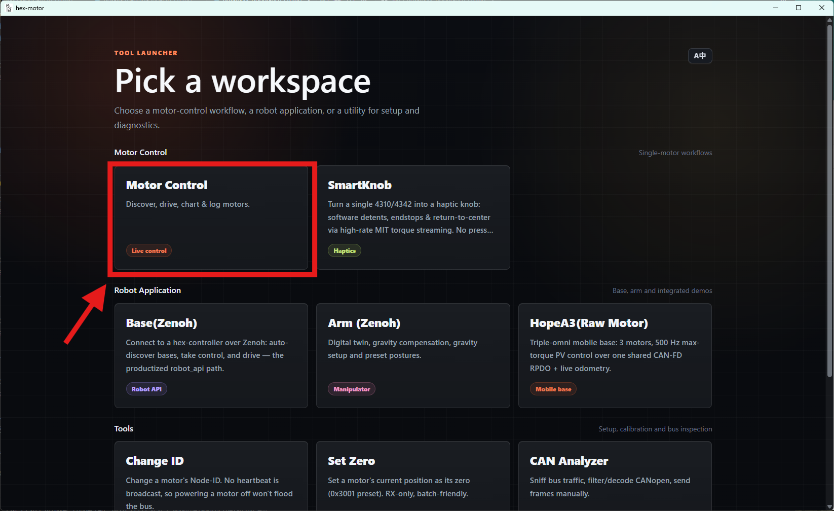
- Open Motor Control.
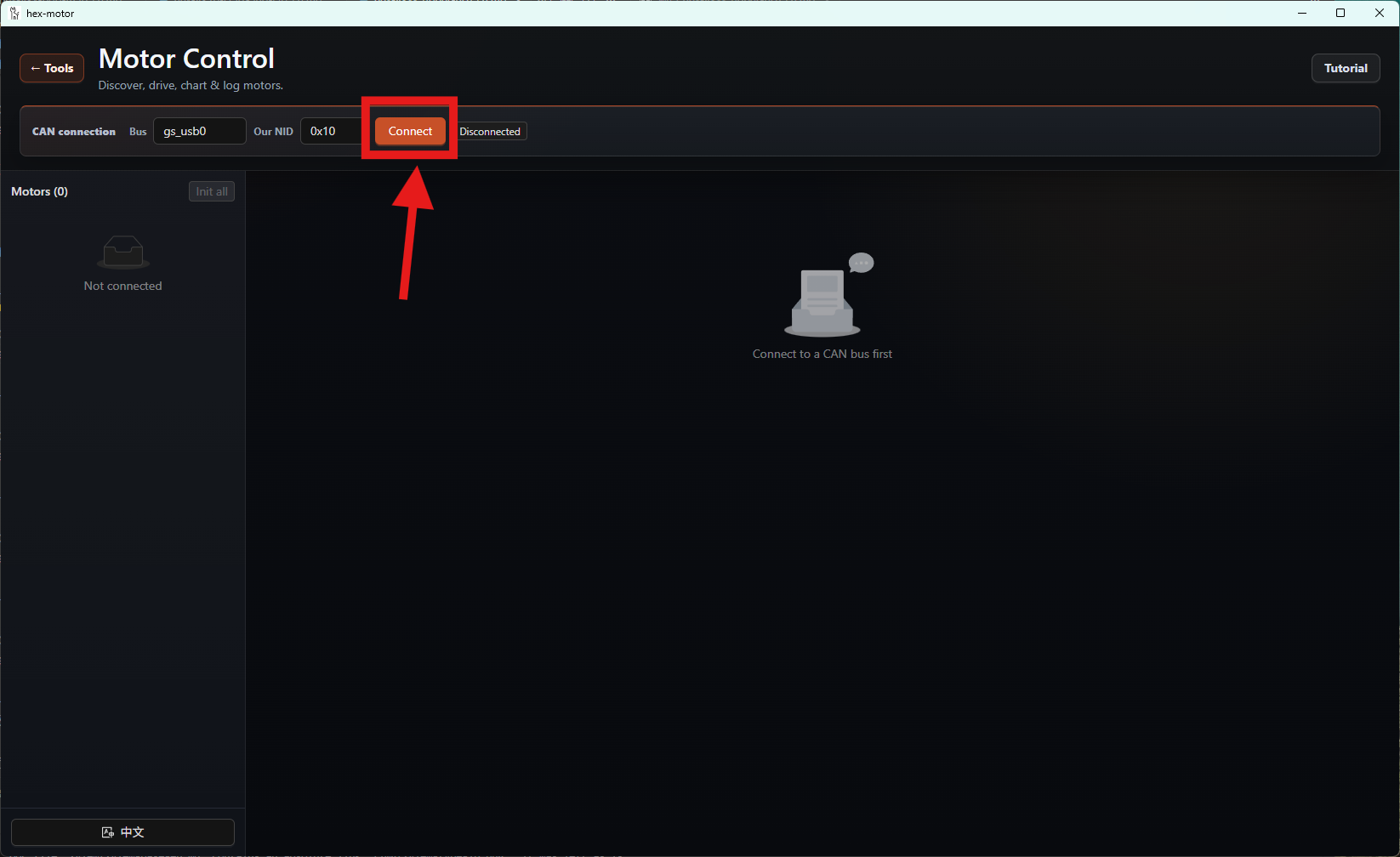
- Set the bus and data bitrate. The default host Node-ID is
0x0A; the motor must have a different ID. - Click Connect and wait for the motor's heartbeat to populate the sidebar.
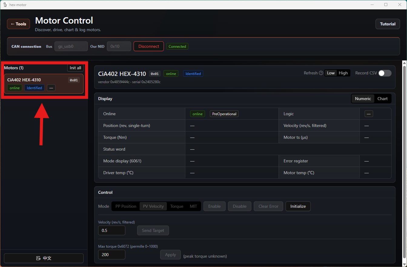
- Select the motor and confirm
hexmeow 4310orhexmeow 4342in the Meow panel. Its Vendor ID / Product Code must match the identity table.
Change Node-ID or timing before motion initialization, using the next section. Otherwise, proceed to initialization and first motion.
Changing the CAN Bus Bitrate on Your Computer
- The images below demonstrate how to change the CAN bus bitrate in the GUI on Windows.
- When using hex-gui on Windows or macOS, you can select the desired bitrate directly next to the CAN interface selector.
- On Linux, you need to configure the CAN bus bitrate separately using the terminal or another tool.
- We also provide can-config, a convenient Linux command-line tool that lets you set your CAN interface's bitrate to match that of hex motors with a single command.
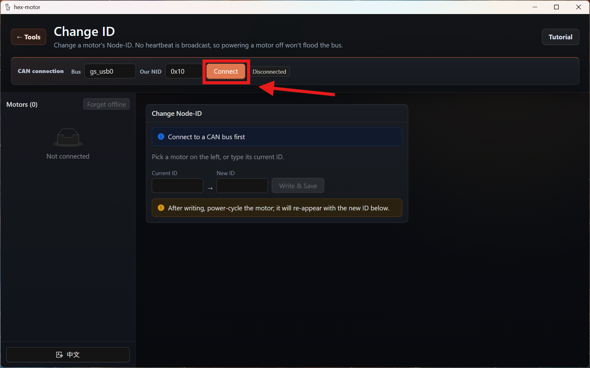
Change Node-ID, timing and BRS
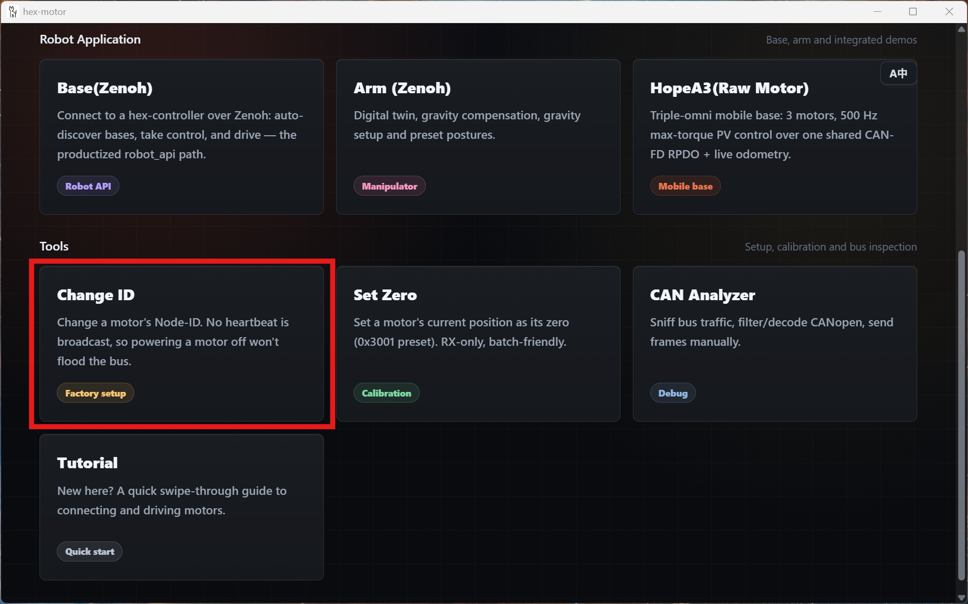
- Open Device Settings, connect and select the motor.
- The motor must be online, not initialized, and NMT Pre-Operational or Stopped. This tool does not send NMT to force that state. After a previous run, disable the motor and power-cycle it before entering the settings tool.
- In CAN settings (object 0x2001), set Node-ID, nominal bitrate, data bitrate and PDO BRS. Keep nominal at 1 Mbit/s for normal GUI use; data supports 1 / 2 / 4 / 5 Mbit/s.
- Click Save and power-cycle. The software writes, reads back and saves through
0x1010:04. - After the success message, manually cycle motor power, match the adapter bitrate and reconnect to verify the new ID. The button does not switch physical power.
The form uses the stored ID, which may differ from the active ID before restart. Confirm the target is unused and avoid host 0x0A and system-reserved IDs 100, 101, 127.
Initialization and first motion
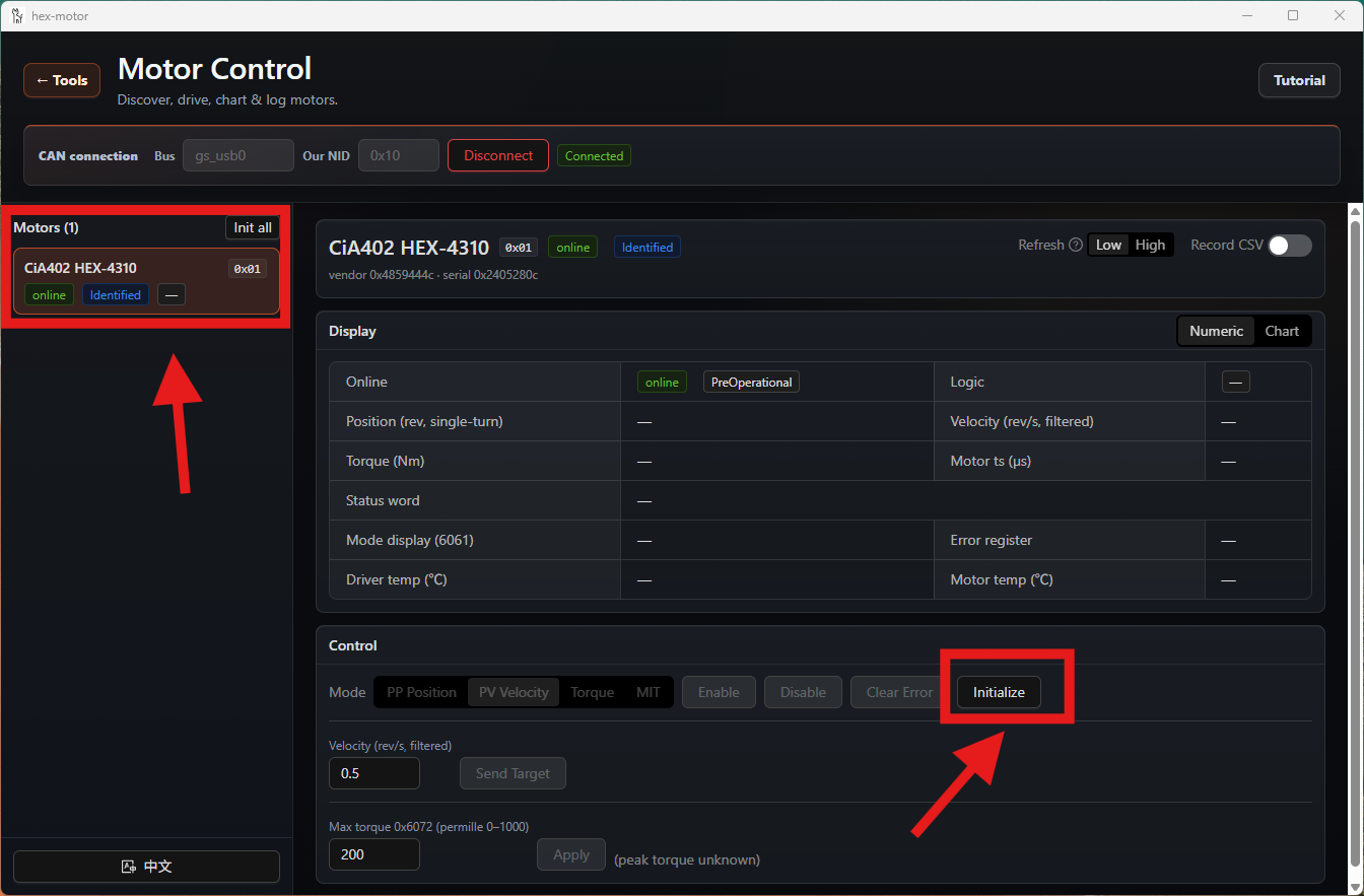
- Return to Motor Control, connect and select the motor.
- Set Device TPDO period to an integer from 1–100 ms. Start with 10 ms (100 Hz) and click Initialize. The GUI's default input is 1 ms; increase it for larger fleets or bus load.
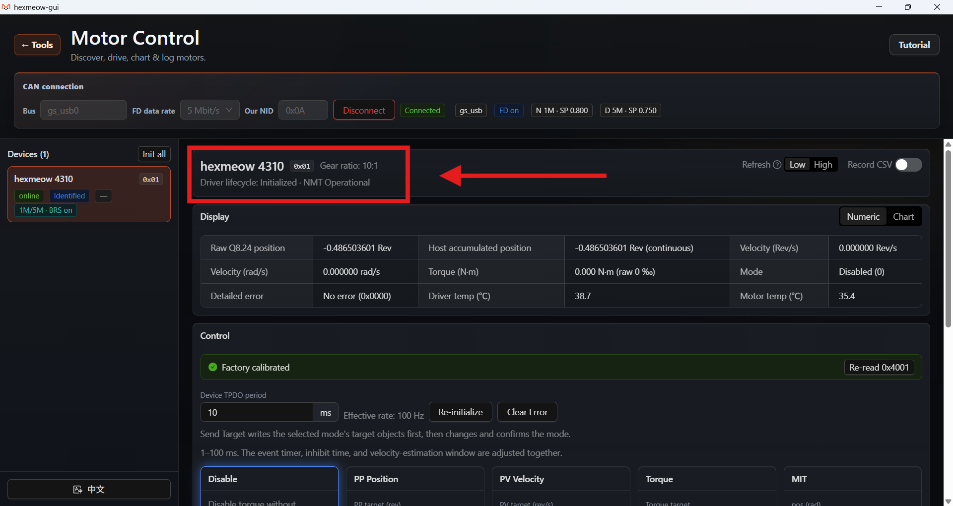
- Wait for lifecycle Initialized, NMT Operational and mode Disabled. Initialization configures feedback and heartbeat while leaving torque disabled.
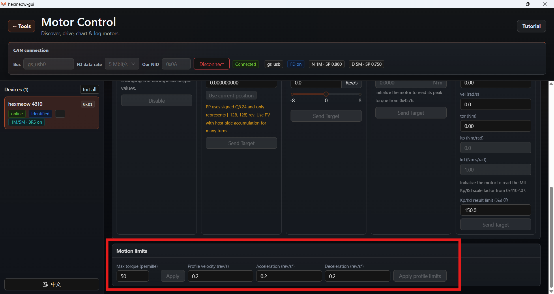
- Under Motion limits, set a low maximum torque such as
50 ‰(5% of raw peak) and click its Apply button. Set suitable low profile velocity, acceleration and deceleration, for example0.2 Rev/s,0.2 Rev/s²,0.2 Rev/s², and click Apply profile limits. Editing fields alone does not write them. Adjust for the load; a low torque cap may be insufficient to start. - In Profile Velocity, enter
0.05 Rev/sand click Send Target. This writes the target, switches to PV and confirms the mode. Motion can start immediately. - Check direction and feedback. Finish by sending
0 Rev/s, observing zero speed, then clicking Disable and confirming its state.
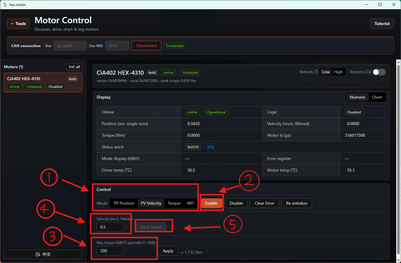
Mode inputs
| Mode | Inputs and behavior |
|---|---|
| PP | Output-shaft Rev, within [-128, 128); use Use current position before a first command to avoid a target jump |
| PV | Output-shaft Rev/s; sign selects direction; suitable for continuous rotation |
| Torque | N·m; the GUI converts using peak torque and factory calibration |
| MIT | rad, rad/s, N·m, Kp (N·m/rad), Kd (N·m·s/rad), Kp/Kd result limit (‰) |
| Disable | Stops torque output without changing configured targets |
Modes can change while enabled. Each card's Send Target writes its target and confirms the mode. The MIT Kp/Kd result limit caps the torque calculated by each term, not the gain values. A zero result limit suppresses the corresponding output.
The GUI currently caps PV input at ±8 Rev/s for 4310 and ±3 Rev/s for 4342. These are input guardrails; operation must still respect hardware ratings and mechanism limits.
Factory torque calibration
Factory calibrated means the GUI applies the torque factor from 0x4001. Factory uncalibrated uses factor 1. On Unavailable, use Re-read 0x4001 and check communication; the current Send Target path rejects requests while the factor is unknown. Do not manually apply the factor again to GUI inputs.
If MIT fields remain unavailable, 0x4102:07 may not have been read. Some older firmware lacks 0x4102. Record the firmware revision and contact the firmware provider.
Feedback, charts and CSV
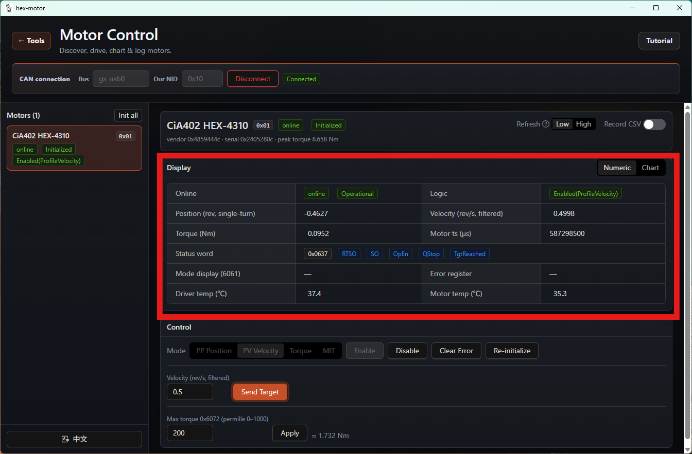
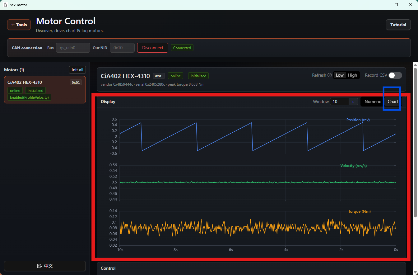
The numeric panel shows converted Q8.24 position in Rev, host accumulated position, velocity, physical torque and raw permille, mode, detailed error and temperatures. The chart plots position / velocity / torque with a 1–60 s window.
The display reads snapshots at 50 or 100 Hz. TPDO1 runs at 1000 / period_ms; TPDO2 is fixed at 50 Hz. Changing display refresh does not change motor feedback timing. Velocity is estimated from position and timestamps; gaps require continuity to be reestablished.
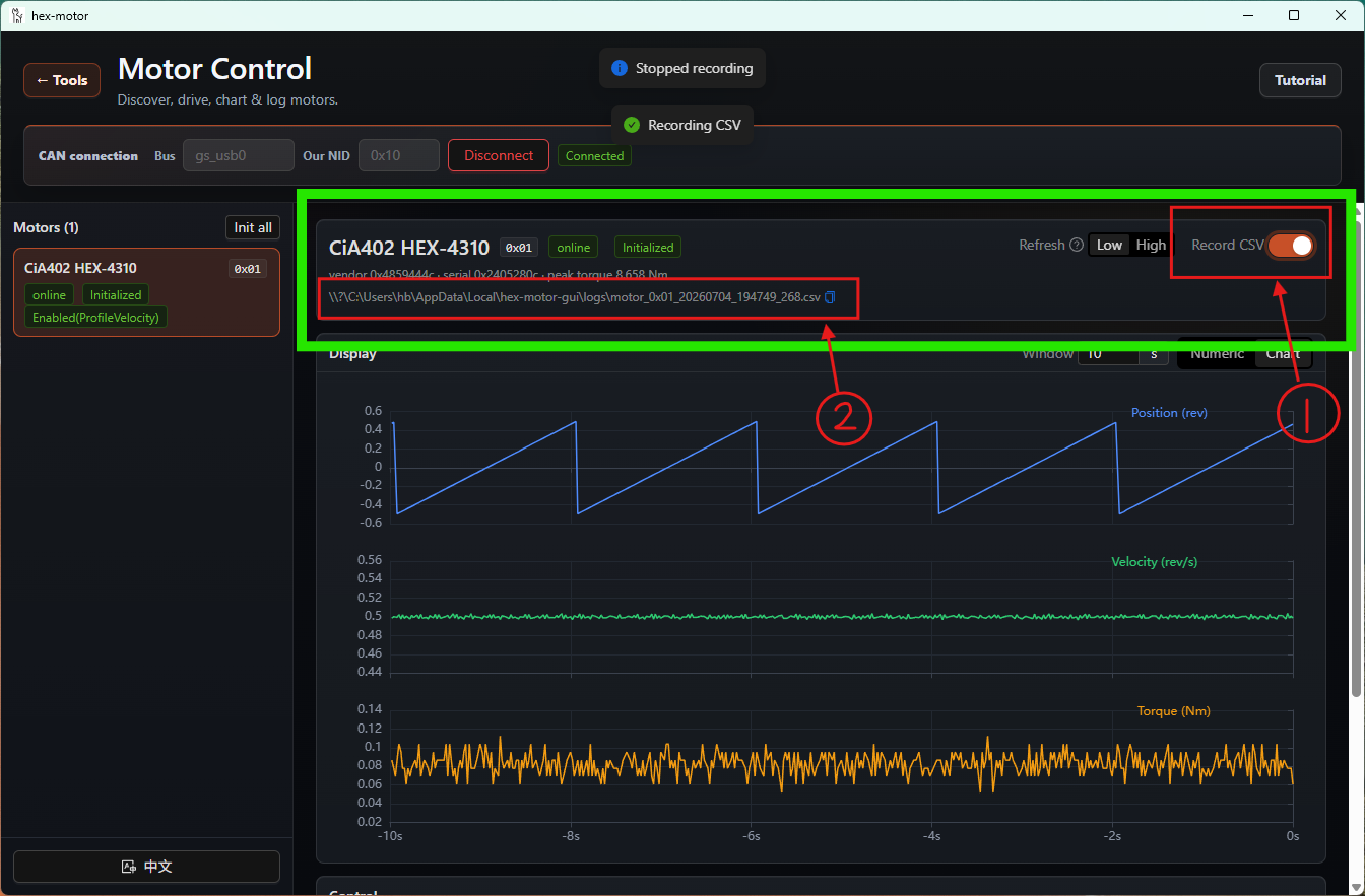
Enable Record CSV to save the driver's publication stream. The GUI shows a copyable path and creates a new file on each recording start. CSV is independent of the 50 / 100 Hz display refresh, but actual reception and logging throughput still limit capture.
Meow CSV stores raw torque_permille, rather than the panel's corrected N·m. Convert it using peak torque and the factory factor during offline analysis. The log also records accumulation validity, segment number and both TPDO generations to help identify gaps.
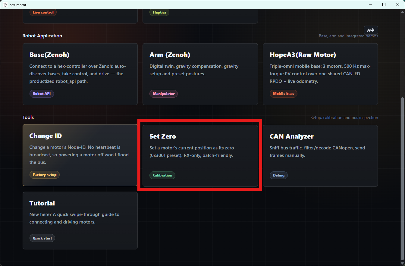
Set the position reference (zero)
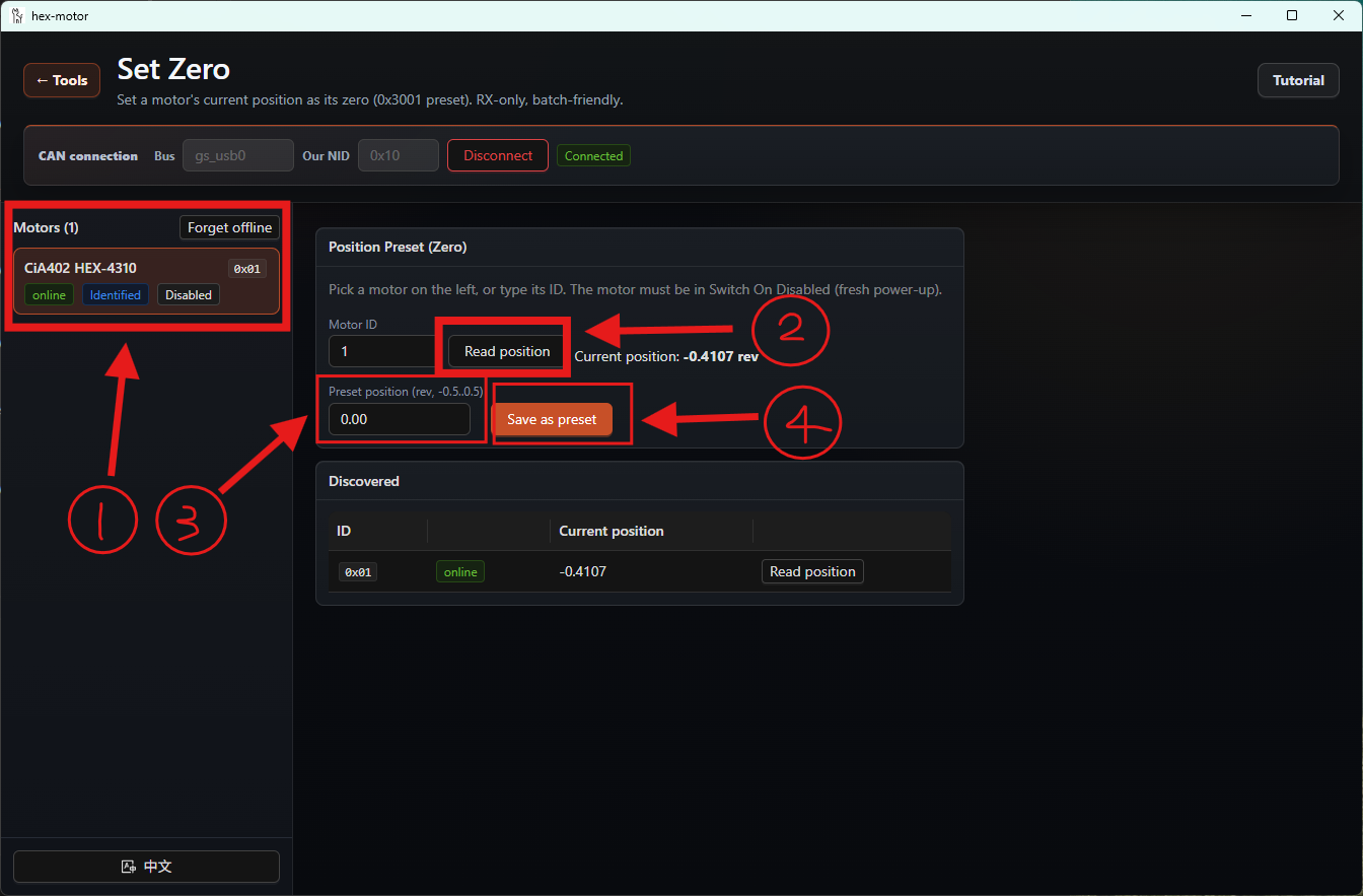
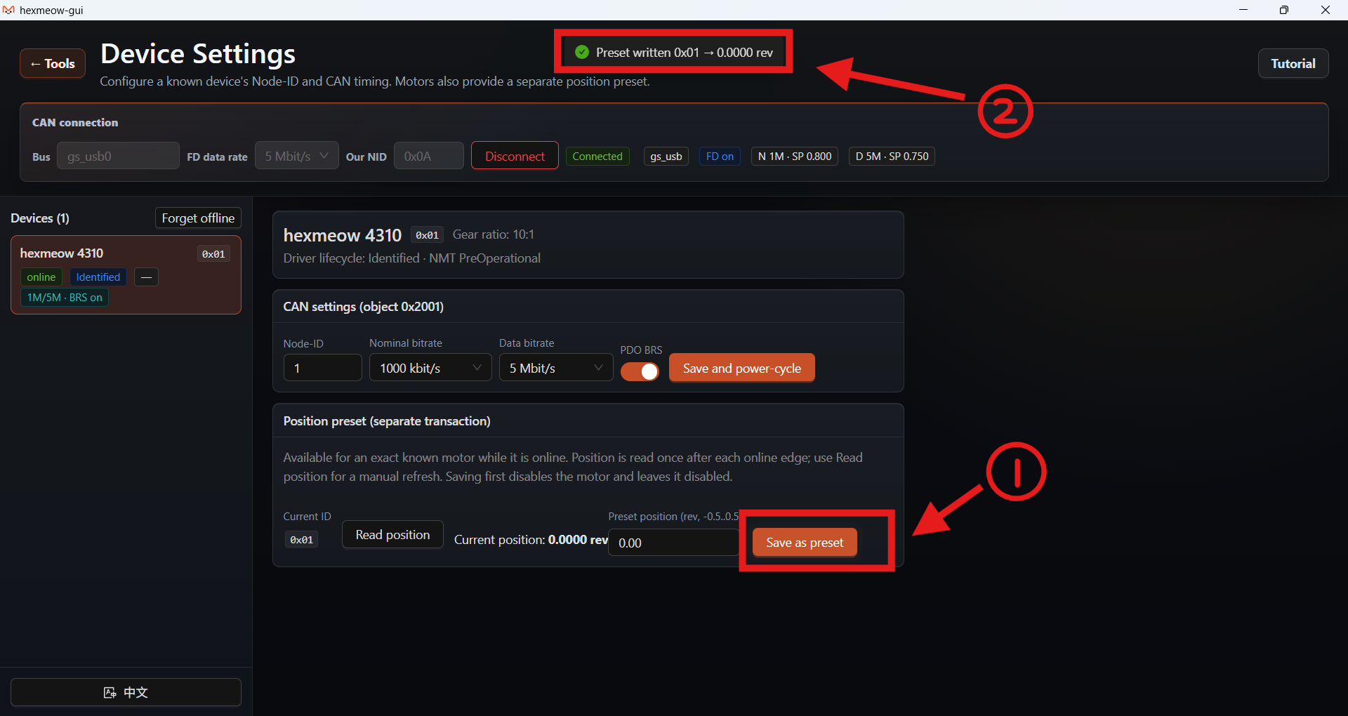
In Device Settings, select an identified online motor and use the separate Position preset card:
- Click Read position and check the value.
- Enter the reference assigned to the current physical position, within -0.5 to 0.5 Rev, for example
0. - Click Save as preset and wait for success and readback. The program first disables and confirms the motor, then writes
0x3001:01followed by0x3001:02 = pres. It remains disabled afterward.
Position preset does not require communication-settings Save and does not move the motor to the entered value. Before resuming motion, return to Motor Control, check state and reinitialize as needed.
Troubleshooting
| Symptom | Check first |
|---|---|
| No motor after connecting | Power, channel, pinout, termination, both bitrates, device heartbeat and duplicate IDs |
| Heartbeat / SDO works but initialization times out | BRS / frame type, PDO mapping and bus load; short FD frames must be accepted |
NeedsRestart |
Settings were saved; manually power-cycle the motor |
NeedsReinit |
Operational state or telemetry was lost; restore the link and initialize again |
0xA4 / 0x8130 |
Continuous host heartbeat and host ID matching 0x1016 |
| Torque / MIT unavailable or command rejected | Readback of peak torque, MIT scale factor and factory data |
ObjectDoesNotExist |
Object address, motor model and firmware revision, especially older 0x4102 support |
| PP out of range / accumulated position discontinuous | PP supports [-128, 128); use PV for continuous rotation and rebuild the baseline after gaps |
See the protocol reference for error codes and communication rules.