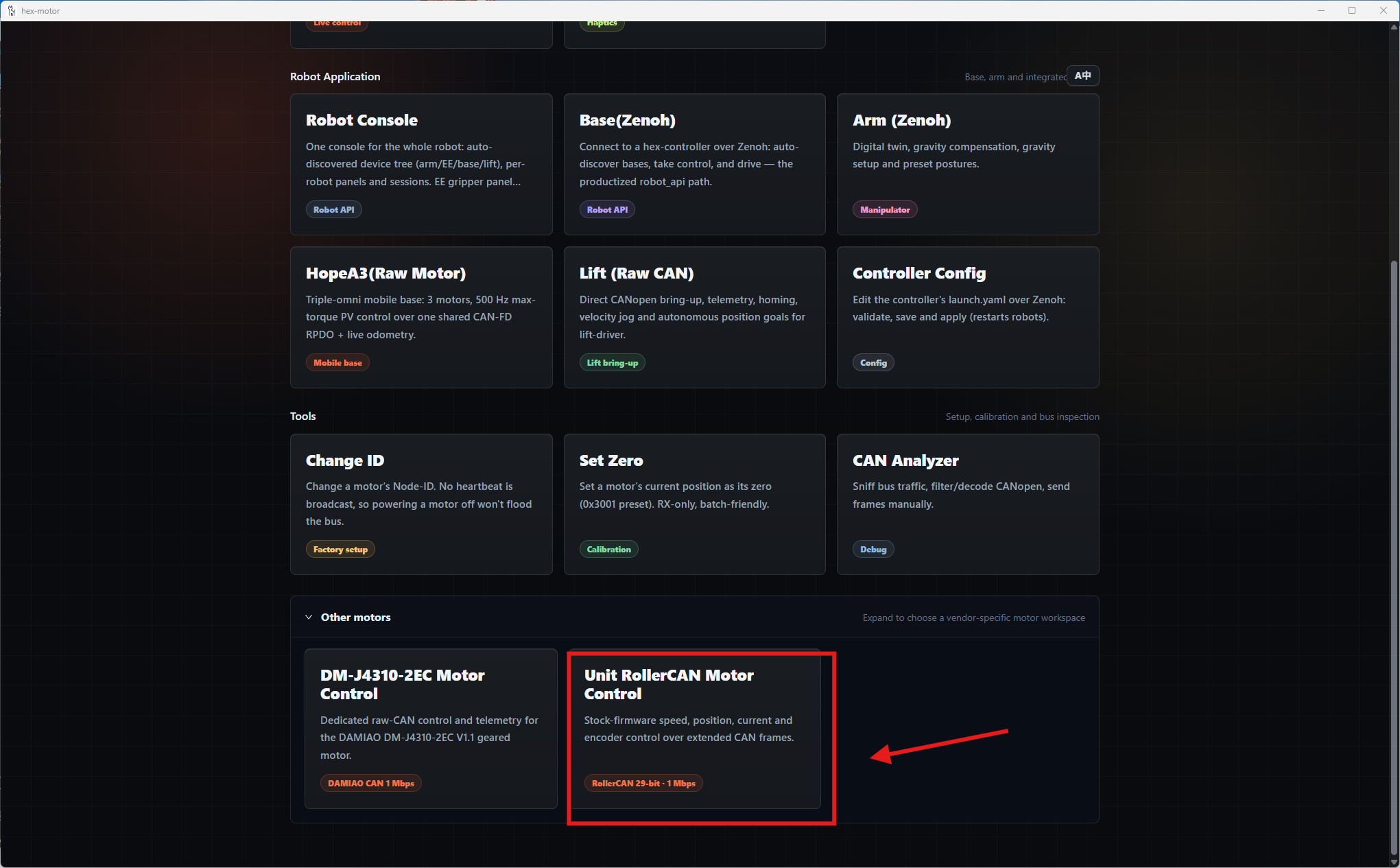
USB-CANFD-HUB
USB-CANFD-HUB is a four-channel USB-to-CAN/CAN FD adapter designed by HexMeow for motor commissioning, robotics development, and general CAN bus analysis.
Key Advantages
Native gs_usb Support on Linux—No Vendor Driver Required
USB-CANFD-HUB implements the gs_usb protocol supported natively by the Linux kernel. When connected to a Linux host, its channels appear as standard SocketCAN interfaces—typically can0 through can3. No vendor-specific driver is required, and the adapter works with iproute2, can-utils, and other SocketCAN applications.
XT30 (2+2) Combines Power and CAN in One Connector
Each of the four CAN FD channels uses an XT30 (2+2) connector that combines power, CAN H, and CAN L in a single plug. It connects directly to HEX 43xx series motors and also works with many CAN motors that use the same connector, including models from DAMIAO and Xiaomi. This greatly reduces power and communication cabling.
Before connecting a third-party motor
Identical connectors do not guarantee identical electrical specifications. Before applying power, verify the motor's rated voltage, connector pinout, CAN bitrate, and termination requirements.
hex-gui Brings CAN Access to Non-Linux Platforms
Linux can access the adapter through SocketCAN, but Windows and macOS do not provide the same native SocketCAN interface. We created the open-source, cross-platform hex-gui application to solve this. Its user-space gs_usb backend accesses USB-CANFD-HUB directly, allowing Windows and macOS systems to send and receive CAN/CAN FD frames correctly.
Other Features
- Four independent CAN FD channels
- High-speed USB Type-C port
- Dedicated power input, with bus power available through the XT30 (2+2) connectors
- Graphical CAN analyzer with raw frame transmission, filtering, and CANopen decoding
- CANopen SDO read and write support
- Graphical control and CAN ID configuration for HEX 43xx series motors
- Connectivity for HexMeow robots and robotic arms, as well as a wide range of third-party CAN devices
Before You Begin
The device has two DIP switches, as shown below.
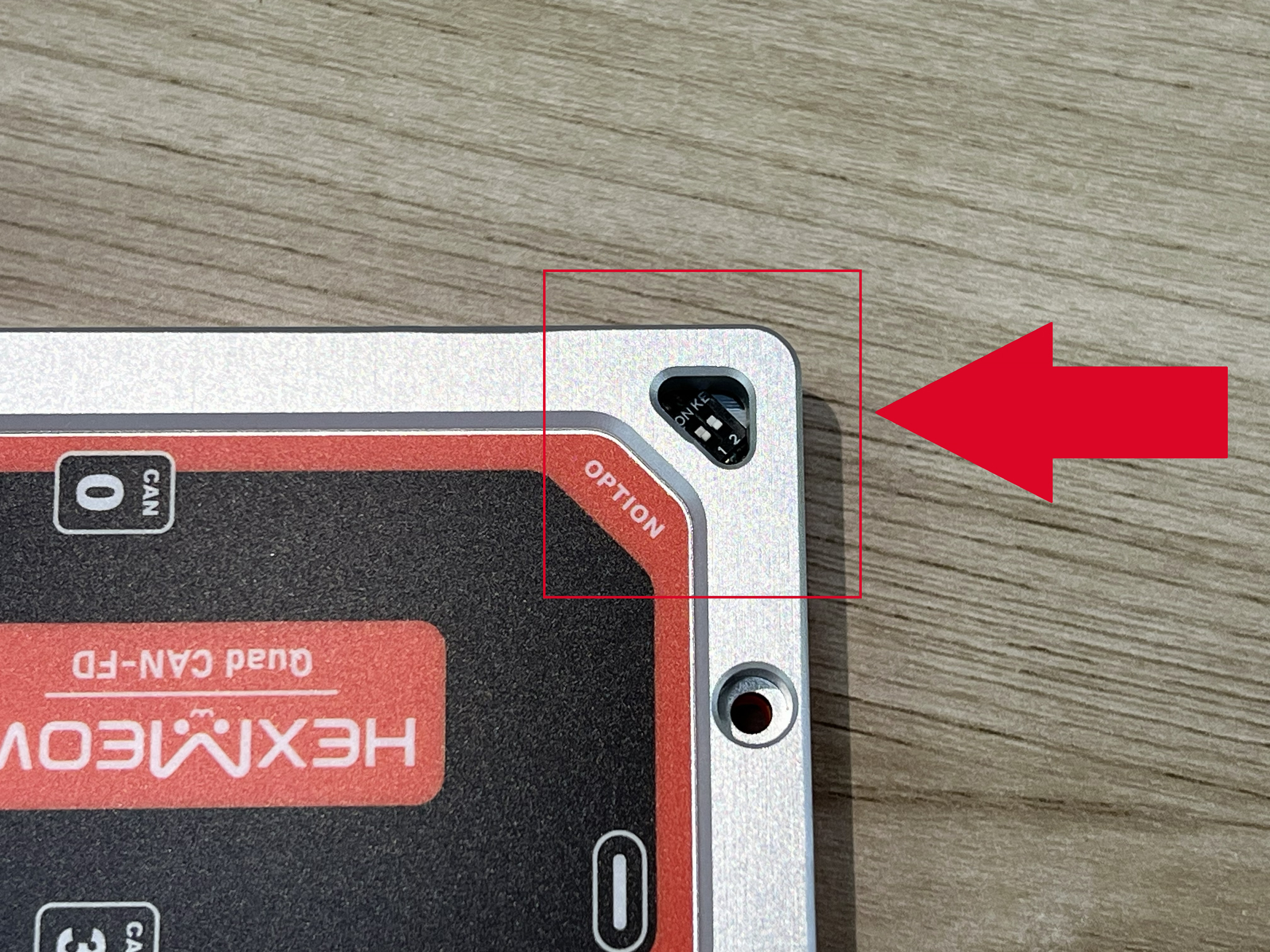
- Switch 1: Move switch 1 to the ON position before powering on the device to enter bootloader mode.
Normal position of switch 1
During normal operation, make sure switch 1 is in the position marked with a number—the OFF position.
- Switch 2: The built-in drivers in some older Linux kernels support only two CAN FD channels, while USB-CANFD-HUB enables all four channels by default. If the device does not work correctly on one of these systems, move switch 2 to the ON position to enable two-channel compatibility mode.
Some older Linux kernels can support all four CAN FD channels after installing a patch. For details, see Four-channel CAN FD support for older Linux kernels.
Wiring and Usage
Check the wiring before applying power
Verify that the supply polarity, voltage, CAN H/CAN L pinout, and termination match the target device before turning on the power.
Selecting a CAN Channel
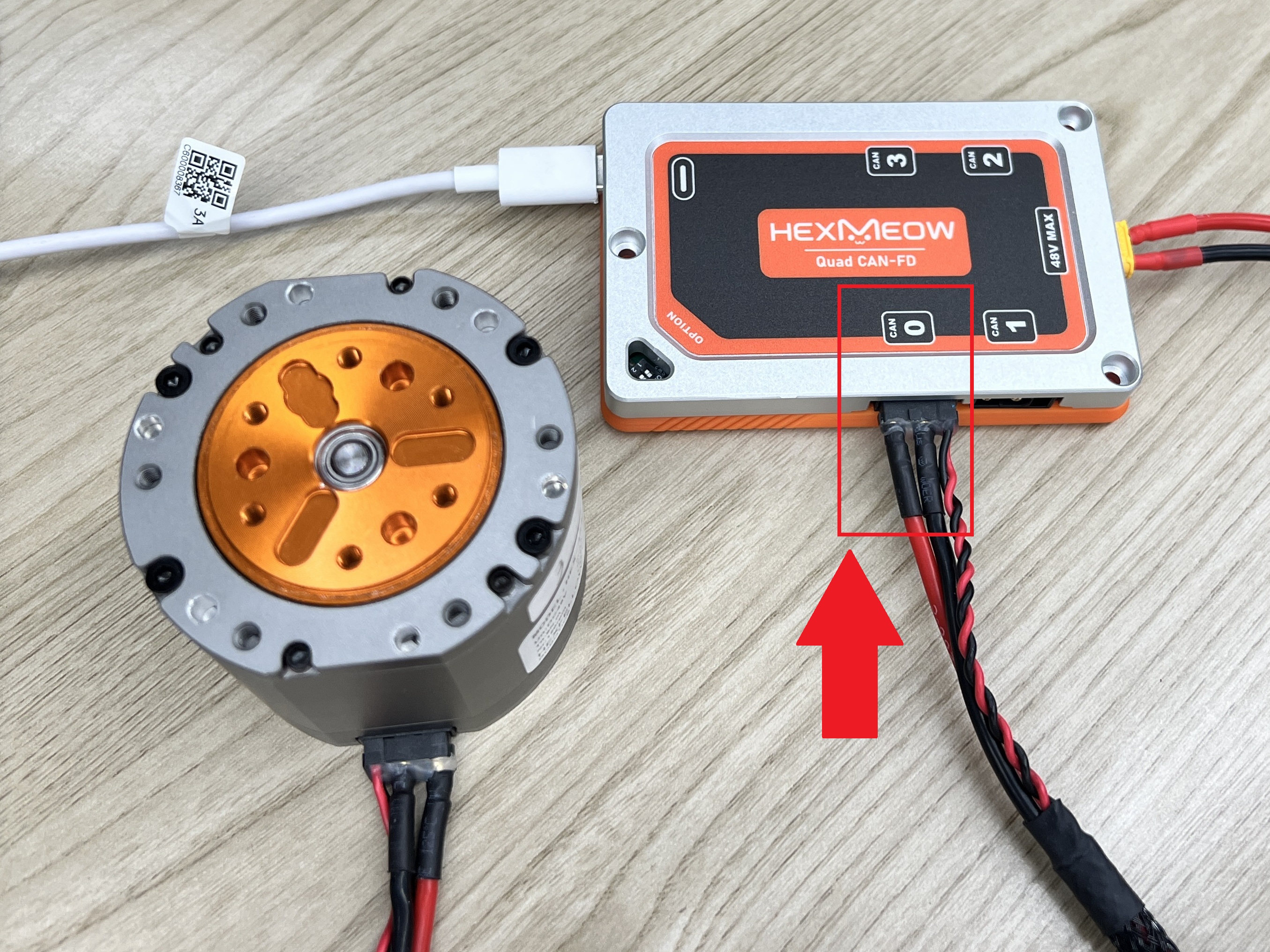
USB-CANFD-HUB provides four CAN FD channels numbered 0 through 3. Use the same channel number for the physical connection and in your software.
All subsequent examples in this guide use CAN channel 0.
The following image shows a motor connected to CAN channel 0:
Interface Name Mapping
| Access method | Platforms | Channel names |
|---|---|---|
| Linux SocketCAN | Linux | can0 through can3 |
hex-gui gs_usb backend |
Linux, Windows, macOS | gs_usb0 through gs_usb3 |
Using SocketCAN on Linux
USB-CANFD-HUB uses the kernel's built-in gs_usb driver, so no vendor-specific driver needs to be installed. The SocketCAN interface must still be configured and brought up before use.
Select the interface that corresponds to the physical channel. The commands below configure CAN channel 0 as can0.
Recommended configuration:
sudo ip link set can0 type can bitrate 1000000 sample-point 0.8 dbitrate 5000000 dsample-point 0.75 sjw 5 dsjw 3 fd on
After configuring the interface, bring it up:
You can now access can0 with can-utils, any SocketCAN application, or hex-gui.
Using USB-CANFD-HUB on Windows and macOS
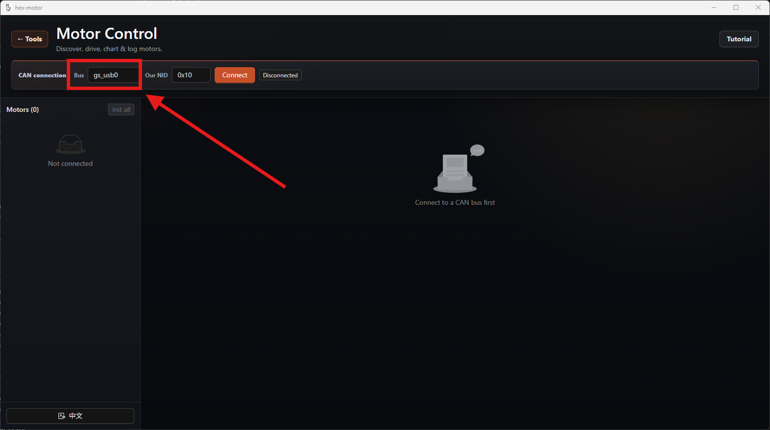
Windows and macOS do not require the Linux ip link initialization commands. Install and open hex-gui, then enter the channel you are using in the Bus field. For example, CAN channel 0 is gs_usb0.
Linux users can also select gs_usbN to access the adapter directly through the hex-gui user-space backend.
The Cross-Platform hex-gui Application
On Linux, USB-CANFD-HUB can integrate with the existing SocketCAN toolchain. To give Windows and macOS users direct CAN access as well, we developed the open-source hex-gui desktop application. Its cross-platform gs_usb backend accesses USB-CANFD-HUB directly without relying on Linux SocketCAN.
Its main features include:
- Sending, receiving, filtering, and recording CAN/CAN FD frames
- CANopen frame decoding and SDO read/write operations
- Discovery, configuration, CAN ID changes, and motion control for HEX 43xx series motors
- Raw CAN frame tools for commissioning third-party devices such as DAMIAO motors and the M5Stack Unit RollerCAN
Prebuilt applications are available from the Releases page. Read the notes for the selected release and download the package that matches your operating system and processor architecture.
Prebuilt packages are recommended
Building hex-gui from source requires Rust, Node.js, and platform-specific system dependencies. Unless you plan to contribute to development, use a prebuilt package from the Releases page.
Using the CAN Analyzer
USB-CANFD-HUB and hex-gui provide a graphical view of CAN traffic. Connect your CAN device to the selected channel, then open CAN Analyzer to begin.
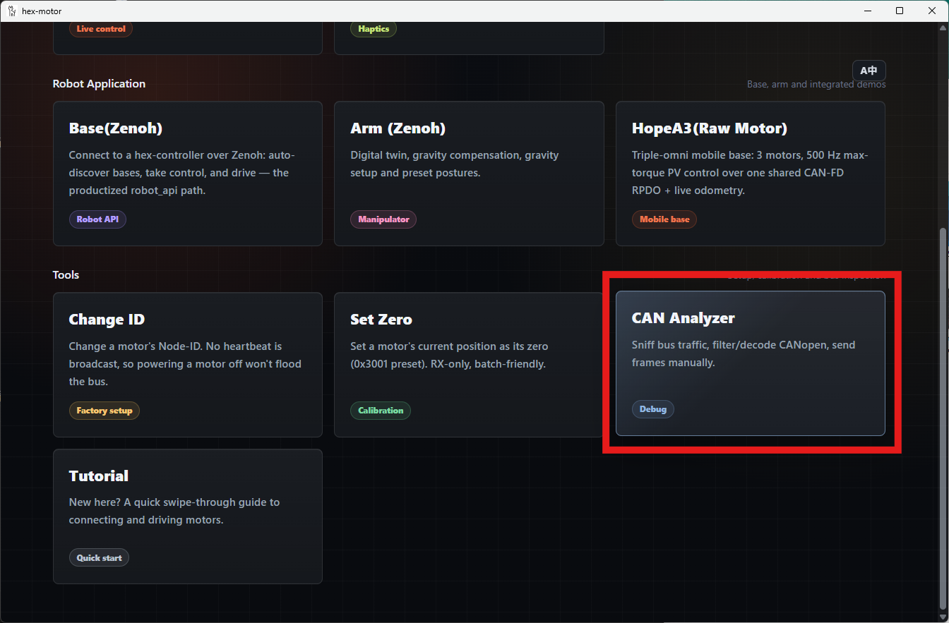
The following examples introduce the main CAN analyzer features.
Controlling HEX 43xx Series Motors (CANopen)
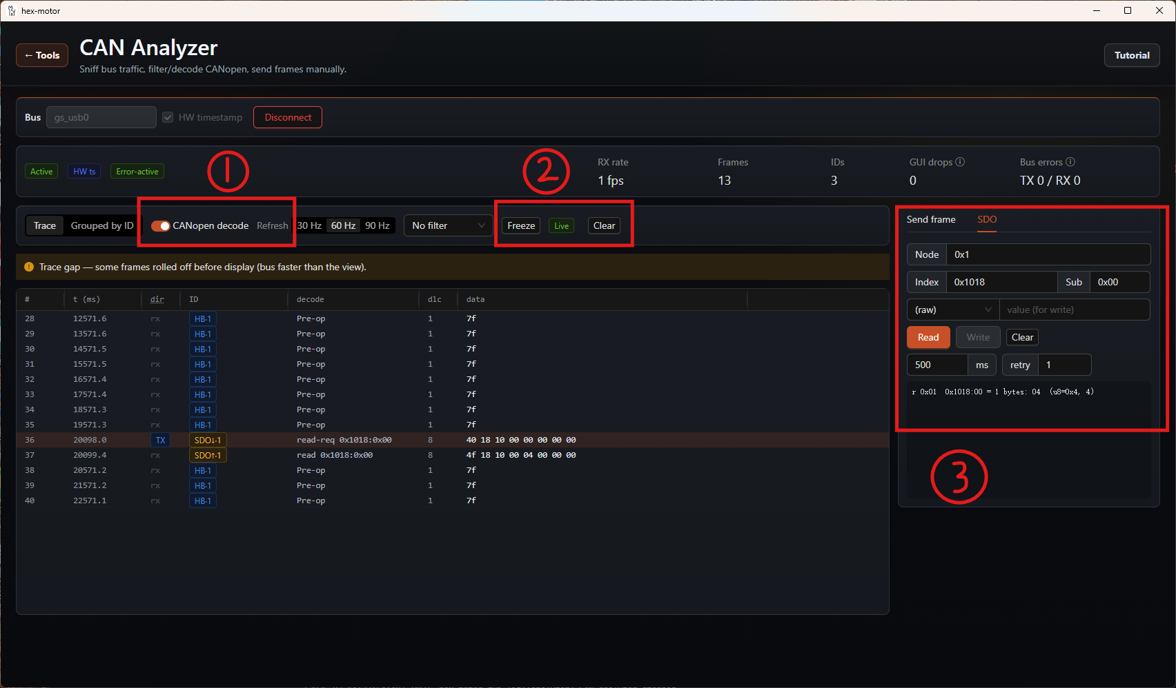
HEX 43xx series motors use CANopen, so this example uses the analyzer's SDO mode to send and receive CANopen messages. You can follow the same procedure with other CANopen devices.
As shown above:
- When using CANopen, enable CANopen decode at ①.
hex-guiidentifies the different CANopen communication types, making each type of message easier to inspect. - To freeze the receive pane and inspect a frame, click Freeze at ②.
- To send an SDO message, select SDO mode at ③. The screenshot shows an SDO read operation; read and write results appear in the status box below.
- You can set the refresh rate to the right of ① or select grouped display to its left, making different CANopen frame types easier to inspect.
Controlling HEX 43xx Series Motors in the GUI
For detailed instructions, see Controlling HEX 43xx series motors with the GUI.
Controlling Other CAN Motors
The CAN analyzer can send and receive standard, extended, and CAN FD frames, so it can also be used to commission third-party motors with proprietary CAN protocols. The following examples use a DAMIAO DM-J4310 and an M5Stack Unit RollerCAN.
DAMIAO DM-J4310 Example
Disclaimer
This example does not replace the DM-J4310 product documentation. Read the motor manufacturer's documentation and assess the risks before proceeding. If successful, the operation shown below will cause the motor to run at 5 rad/s.
As shown above:
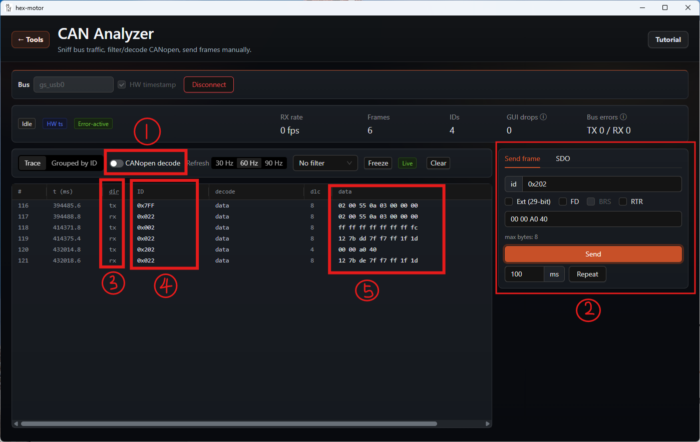
- The
DM-J4310in this example does not use CANopen, so first disable CANopen decode at ①. - Select Send frame at ② to compose and transmit a raw CAN frame. Select the extended frame format, then enter the corresponding CAN ID and data. The central trace pane displays the transmitted and received frames.
- ③ identifies a frame as received (RX) or transmitted (TX).
- ④ shows the CAN ID.
- ⑤ shows the frame data.
DM-J4310 Motor Control
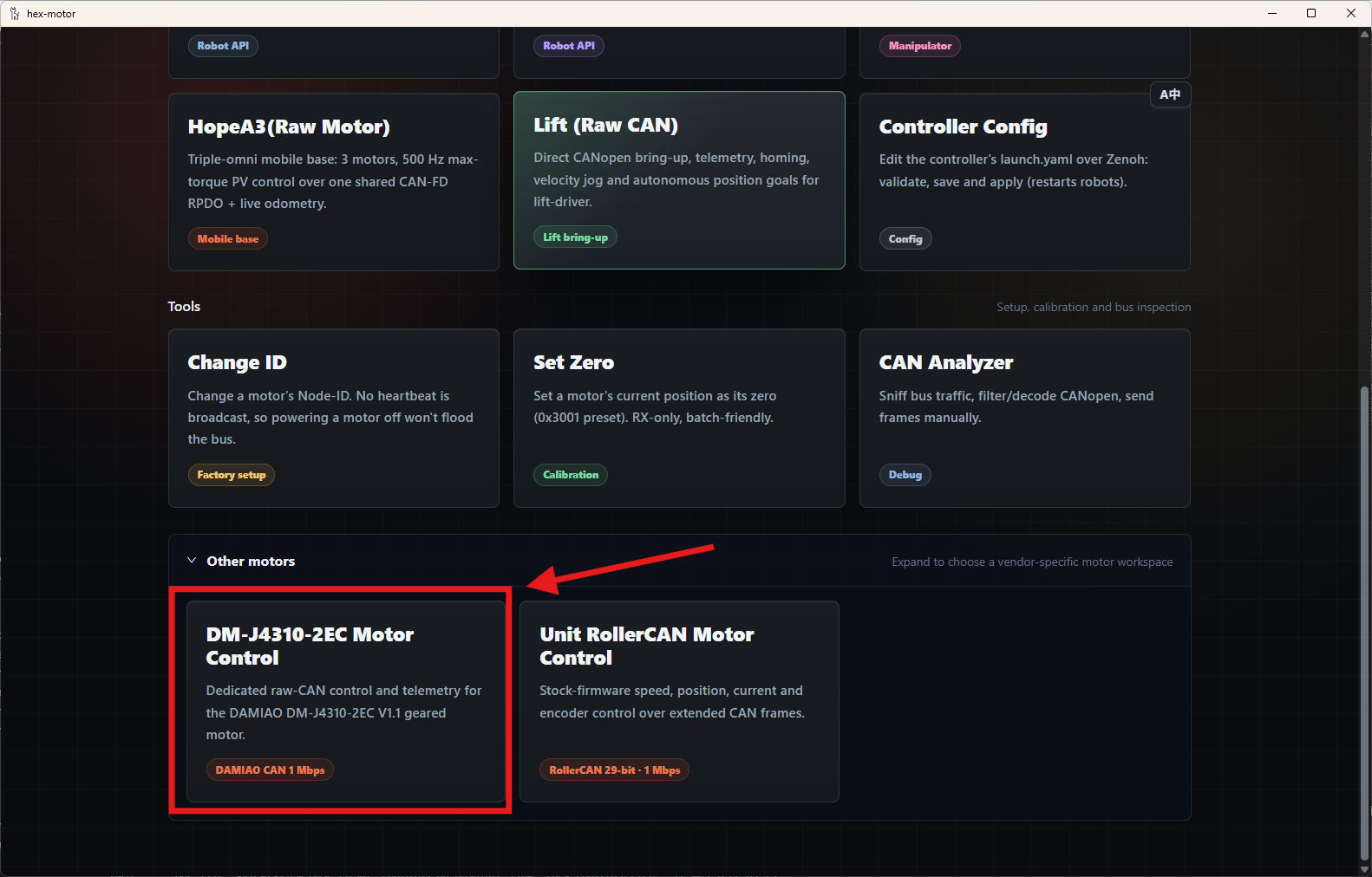
hex-gui also provides a dedicated graphical motor control panel for the DM-J4310. Its basic workflow is the same as for HEX 43xx series motors.
For detailed instructions, see Controlling HEX 43xx series motors with the GUI.
M5Stack Unit RollerCAN Example
Disclaimer
This example does not replace the M5Stack Unit RollerCAN product documentation. Read the motor manufacturer's documentation and assess the risks before proceeding.
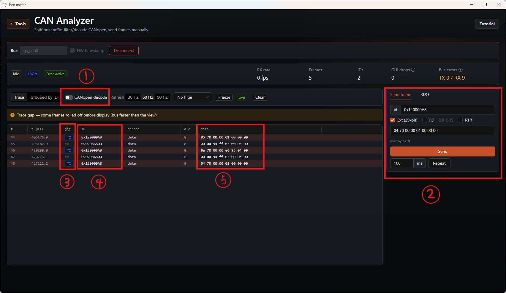
As shown above:
- The
M5Stack Unit RollerCANin this example does not use CANopen, so first disable CANopen decode at ①. - Select Send frame at ② to compose and transmit a raw CAN frame. Select the extended frame format, then enter the corresponding CAN ID and data. The central trace pane displays the transmitted and received frames.
- ③ identifies a frame as received (RX) or transmitted (TX).
- ④ shows the CAN ID.
- ⑤ shows the frame data.
Smart Knob
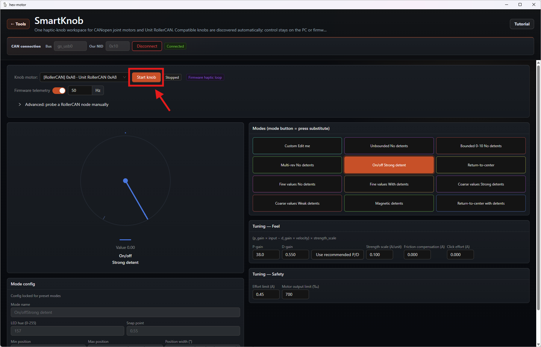
We also provide smart force-feedback knob firmware for the M5Stack Unit RollerCAN. After flashing the firmware, connect the motor to USB-CANFD-HUB in CAN mode and open SmartKnob in hex-gui to use the motor as a smart force-feedback knob.
RollerCAN Control
hex-gui also provides a dedicated graphical motor control panel for the M5Stack Unit RollerCAN. Its basic workflow is the same as for HEX 43xx series motors.
For detailed instructions, see Controlling HEX 43xx series motors with the GUI.