Quick Start & Configuration
CAN Configuration
Hardware Configuration
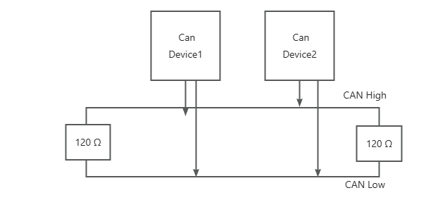
Termination resistors must use split termination. Star topology is not allowed. Make sure there are exactly two termination resistor groups on the same CAN line, both located at the two ends of the line.
As shown below:
Software Configuration
The motor uses CAN-FD. The arbitration phase is fixed at 1 Mbps with a sample point of 0.8. The data phase bitrate is fixed at 5 Mbps with a sample point of 0.75.
Recommended CAN configuration command:
ip link set can0 type can bitrate 1000000 sample-point 0.8 dbitrate 5000000 dsample-point 0.75 sjw 5 dsjw 3 fd on
Once the CAN configuration succeeds, bring the CAN interface up:
Note
The sample point must be set correctly, otherwise sending long frames will definitely cause communication failure. Some USB-to-CAN devices may not correctly support setting these parameters. If you encounter this situation, please use an SoC with hardware CAN-FD support such as the RK3576.
Configuring the Motor ID
Our motors use the CANopen (CiA301) protocol. CANopen is widely used in industrial automation and there are many tutorials online, so we won't go over it in detail here. We did make one small change regarding PDOs: the maximum PDO length is allowed to be 64 bytes, in order to make full use of the CAN-FD bandwidth.
If you want to learn about the CANopen protocol, see: CANopen Explained
The CAN-ID is set through object dictionary entry 2001h, 1h.
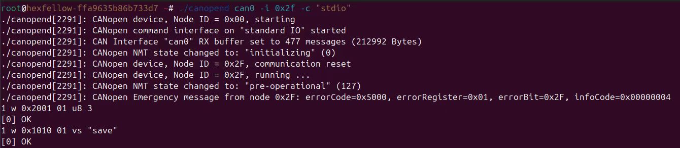
For example, using the canopend tool to change motor No. 1 to No. 3:
For how to use the canopend tool, please refer to its GitHub documentation; we won't explain it here.
./canopend can0 -i 0x30 -c stdio    # Start the Canopend tool
1 w 0x2001 01 u8 3                  # Change Motor No. 1 to Motor No. 3
1 w 0x1010 01 vs "save"             # Input save command
The new ID takes effect after a power cycle
Once the new ID is set, it only takes effect after a power cycle. Please be careful not to set the wrong ID.
An "ok" response after sending the SDO means the setting succeeded.
Breakdown of the SDO command used to change the ID above
### Command explanation Write a `uint8_t` value of `3` to object dictionary `0x2001:01` of node 1.### SDO request CAN frame ### COB-ID breakdown So the CAN ID of this request frame is: ### Data field breakdown
Byte0 : 0x2F
Byte1 : 0x01
Byte2 : 0x20
Byte3 : 0x01
Byte4 : 0x03
Byte5 : 0x00
Byte6 : 0x00
Byte7 : 0x00
Control Test with canopend
Below we'll use the canopend tool for a simple control test.
Proceed with caution
Before starting motor control, make sure the surrounding environment is safe. Because repeatedly sending a node's heartbeat from the terminal is not very convenient, neither of the two examples here uses heartbeat timeout detection.
SDO control test
About the SDO control test
In practice you should use PDOs to write objects such as 60FFh, but here we first use SDO to demonstrate CAN communication.
Proceed with caution
Before starting motor control, make sure the surrounding environment is safe.
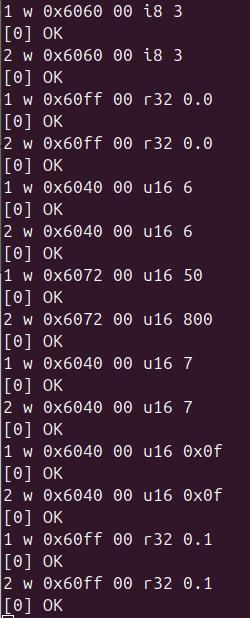
Before we start, power-cycle the motors to make sure they are in their initial state. Assume the motors to control are 0x01 and 0x02. We'll demonstrate using velocity mode, with motor 1's torque limited to 5% of peak torque and motor 2's limited to 80% of peak torque.
1 w 0x6060 0 i8 3
2 w 0x6060 0 i8 3
1 w 0x60FF 0 r32 0
2 w 0x60FF 0 r32 0
1 w 0x6040 0 u16 6
2 w 0x6040 0 u16 6
1 w 0x6072 0 u16 50
2 w 0x6072 0 u16 800
After all of the above have been written, write 7 to the control word:
Finally write 0x0f:
The motors are now enabled, with a target of 0 rev/s. Just write the speed as a Float32. Here we'll test at 0.1 rev/s.
Both motors now start rotating at 0.1 rev/s. Because the two motors have different maximum torque, one stops with only a small applied resistance, while the other requires a much larger resistance to stop.
PDO control test
Clearly, SDO communication wastes a lot of bandwidth. You should use PDOs for control as much as possible. But as mentioned earlier, the PDO mapping must be adjusted according to the actual number of motors you operate, so this demo still only shows the case of controlling 4 motors; adjust for other cases as appropriate.
Adjusting the PDO mapping
In CANopen, a PDO COB-ID can be configured as needed. By assigning the same RPDO COB-ID to several motors, the host can update each motor's target values with one CAN-FD frame. This requires changing both the RPDO COB-ID and the RPDO mapping on every controlled motor.
Sounds a bit abstract?
Take velocity control with a torque limit as an example. Each motor uses 6072h (Max Torque, 2 bytes) and 60FFh (Target Velocity, 4 bytes), for 6 bytes per motor. Four motors therefore require 24 bytes, which fit in one CAN-FD frame.
Assume the four motors have CANopen IDs 0x01, 0x02, 0x03, and 0x04. Choose an unused COB-ID and configure RPDO1 on all four motors to receive that COB-ID.
This example uses 0x190. It is conventionally the TPDO1 COB-ID of node 0x10, but here it is simply the CAN-ID on which the host sends the shared control frame. The important requirement is that it must not conflict with any other frame on the bus.
The 24-byte payload is arranged as follows:
The 4-byte padding object is 3000h 03h; the 2-byte padding object is 3000h 02h.
Motor 1 Max Torque (2 Bytes) | Motor 1 Target Velocity (4 Bytes) | Motor 2 Max Torque (2 Bytes) | Motor 2 Target Velocity (4 Bytes) | Motor 3 Max Torque (2 Bytes) | Motor 3 Target Velocity (4 Bytes) | Motor 4 Max Torque (2 Bytes) | Motor 4 Target Velocity (4 Bytes)
| Byte offset | Contents |
|---|---|
| 0–1 | Motor 1: 6072h |
| 2–5 | Motor 1: 60FFh |
| 6–7 | Motor 2: 6072h |
| 8–11 | Motor 2: 60FFh |
| 12–13 | Motor 3: 6072h |
| 14–17 | Motor 3: 60FFh |
| 18–19 | Motor 4: 6072h |
| 20–23 | Motor 4: 60FFh |
Each motor maps only its own 6-byte slot to active objects and maps the other 18 bytes to the 3000h padding objects. All four motors receive the same frame, but each motor updates only its own targets.
Motor 1 uses the following mapping:
Max Torque 6072h | Target Velocity 60FFh | 4-byte padding | 4-byte padding | 4-byte padding | 4-byte padding | 2-byte padding
For motor 2, its RPDO mapping should look like this:
4-byte padding | 2-byte padding | Max Torque 6072h | Target Velocity 60FFh | 4-byte padding | 4-byte padding | 4-byte padding
For motor 3, its RPDO mapping should look like this:
4-byte padding | 4-byte padding | 4-byte padding | Max Torque 6072h | Target Velocity 60FFh | 4-byte padding | 2-byte padding
For motor 4, its RPDO mapping should look like this:
4-byte padding | 4-byte padding | 4-byte padding | 4-byte padding | 2-byte padding | Max Torque 6072h | Target Velocity 60FFh
For example, setting every motor's max torque to 800 (80% of peak torque) and target velocity to 1.0 rev/s produces this 6-byte group for each motor:
20 03 is the little-endian Uint16 representation of 800, and 00 00 80 3F is the little-endian Float32 representation of 1.0. Repeating the group four times produces one 24-byte CAN-FD frame that updates all four motors.
Saving the PDO mapping
The PDO mapping can be saved so you don't have to reconfigure it on every power-up. See object 1010h for details. Once saved, on each boot you only need to send the NMT command to start controlling right away.
About the padding objects
You don't have to stick to this exact layout — thanks to the flexibility of PDOs, you can arrange things freely. Suppose the target velocity actually needs to change at a higher frequency while the max torque does not; then you can put all the max-torque objects into RPDO2, sending the target velocity at a high rate and the max torque at a low rate.
You also don't have to force all motors into the same control mode: some motors can run in velocity control mode while others use MIT control mode. As long as the mapping is correct, it works.
About configuration automation and persistence
Remember that canopend essentially just sends some CAN messages, so you can fully automate the PDO configuration process. For the exact format of the SDO protocol, please refer directly to the many tutorials available online.
Also, unless these settings are saved via object 1010h, they revert to their default configuration after every power-up. If you are sure you won't change these settings, simply save via object 1010h to make the configuration persistent. On subsequent boots there is no need to reconfigure — you only need to send the NMT command, select the mode, and manipulate the control word.
The following concrete sequence configures motor 2. Motor 2 uses bytes 6–11 of the shared frame, so its mapping begins with 4-byte and 2-byte padding objects. Motors 1, 3, and 4 must each go through the same configuration sequence using the mapping shown above for their own byte slots. All four RPDO1 COB-IDs are set to 0x190.
- First write
0x8000_0000 | 0x190to 1400h 01h to disable RPDO1 - Set 1400h 02h (transmission type) to 255
- Set 1600h 00h (number of valid RPDO mappings) to 0
- Set 1600h 01h, application object 1, to 4-byte padding 3000h 03h
- Set 1600h 02h, application object 2, to 2-byte padding 3000h 02h
- Set 1600h 03h, application object 3, to Max Torque 6072h 00h
- Set 1600h 04h, application object 4, to Target Velocity 60FFh 00h
- Set 1600h 05h, application object 5, to 4-byte padding 3000h 03h
- Set 1600h 06h, application object 6, to 4-byte padding 3000h 03h
- Set 1600h 07h, application object 7, to 4-byte padding 3000h 03h
- Set 1600h 00h (number of valid mappings) to 7
- Finally write
0x0000_0000 | 0x190to 1400h 01h to enable RPDO1
After configuring the individual RPDO mappings on motors 1–4, enter 0 start to broadcast NMT Start and put every node into the CiA301 Operational state. If you do not want to broadcast, send start to nodes 1–4 individually.
PDO control is not yet available because the CiA402 state machine has not been configured. Perform the following sequence once for each motor:
- Write
0x80to 6040h 00h to clear faults - Write
0x03to 6060h 00h to set the motor to velocity control mode - Write
0x06to 6040h 00h — Shutdown - Write
0x07to 6040h 00h — Switch On - Write
0x0fto 6040h 00h — Operation Enable
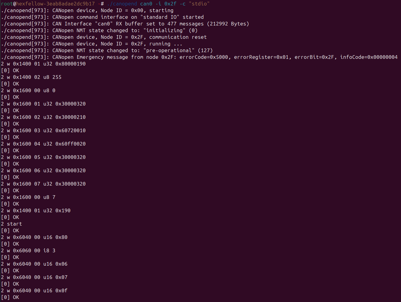
The motor can now be controlled via PDO. Below is an example that limits every motor's max torque to 80% with a target speed of 1 rev/s.
The 24-byte payload consists of four 20 03 00 00 80 3F groups. Each group contains one motor's max torque followed by its target velocity:
The host sends only one CAN-FD frame with COB-ID 0x190. When the mappings are correct, all four motors read their own 6-byte slots and start running together.
Quick Start: Full Control Demo
If you'd like to first get a complete pipeline working — from cold start to continuous operation — see the open-source repository hex-motor-control-test. It provides two minimal C demo programs (not libraries) that drive hexfellow motors via CAN-FD, CANopen (CiA301 + CiA402), and the 64-byte PDO extension:
| Program | Description |
|---|---|
demo_mit |
MIT mode (6060h = 5): runs all motors at a constant speed |
demo_velocity |
Profile velocity mode (6060h = 3): runs at a constant speed and limits torque via 6072h in every frame |
The demo covers: per-motor SDO initialization, NMT into Operational, CiA402 enable, master heartbeat and a shared RPDO control loop, and TPDO telemetry printing. It assumes by default that motor CANopen IDs are numbered consecutively from 1, up to 8 motors, and that the firmware version is 08.
First configure the CAN interface for CAN-FD as described above, then build and run (using 4 motors, can0, and 0.5 rev/s as an example):
See the repository README for more parameters, cross-compilation, heartbeat/RPDO timing conventions, and other details.
For demonstration only
This repository is for learning and bench validation only — it is not production-grade software and has no proper error recovery or safety interlocks. Before using it in any scenario that could cause injury or loss, please audit it yourself and write a driver suitable for your product.
ESP32-C5 control demo program
If you want to control motors with a microcontroller, see hex-motor-esp-control-example. This demo uses the ESP32-C5 with ESP-IDF as the development framework in C++, driving hexfellow motors via CAN-FD, CANopen (CiA301 + CiA402), and the 64-byte PDO extension.
The demo wraps a FreeRTOS motor-control task class — HexfellowMotorTask. This task class performs, per motor, SDO initialization, NMT into Operational, CiA402 enable, master heartbeat and a shared RPDO control loop, and receives the motor's running state via TPDO.
It also uses a serial I/O task to provide real-time feedback and to adjust the motors' running state. By default it only outputs the state data of the motor with ID 1. Enter the following commands over the serial port to adjust the speed of the motor with ID 1 in real time:
spd 2.5       # motor 0 → 2.5 rev/s
spd 0         # motor 0 → stop
spd -1.0      # motor 0 → reverse 1.0 rev/s
spd ?         # print current velocity
By default it only controls one motor with ID 1. If you want to control multiple motors, modify the count member of HexfellowMotorController::Config and write the corresponding control parameters into the motors member of HexfellowMotorController::Config. Thanks to the flexibility of PDOs, you can configure different motors to use different operating modes within a single RPDO, as long as the motors' RPDO mapping is correct.
For example, to drive two motors with motor 0 in MIT mode and motor 1 in velocity mode:
HexfellowMotorController::Config cfg;
cfg.count = 2;      // change the number of motors to drive here
// motor 0, default MIT mode
cfg.motors[0].mode = HexfellowMotorController::HEXFELLOW_MODE_KIND_MIT;
cfg.motors[0].torque_permille = 300;
cfg.motors[0].kp_kd_torque_permille = 770;
HexfellowMotorController::mit_mapping_default(cfg.motors[0].mapping);
// motor 1: velocity mode
cfg.motors[1].mode = HexfellowMotorController::HEXFELLOW_MODE_KIND_VELOCITY;
cfg.motors[1].torque_permille = 300;   // max torque limit for velocity mode
For more details about this demo, see the README in the repository.
Using the GUI
The motor GUI used in this chapter requires our GUI USB hardware — the USB-CAN HUB.
Downloading the GUI
Wiring and Usage
The GUI hardware already integrates a termination resistor for every CAN interface, so when using the GUI you do not need to add a termination resistor at the GUI-side end of the CAN line — you only need to add one at the motor-side end of the CAN line.
Then connect it to your computer with a single Type-C data cable.
The CAN interface must be initialized
On Linux or macOS you must initialize the CAN interface before you can connect to the motors. See the recommended command for bringing up the CAN interface at the beginning of this document.
Changing a Motor ID with the GUI
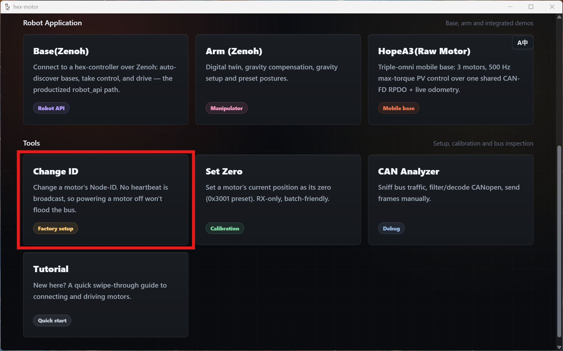
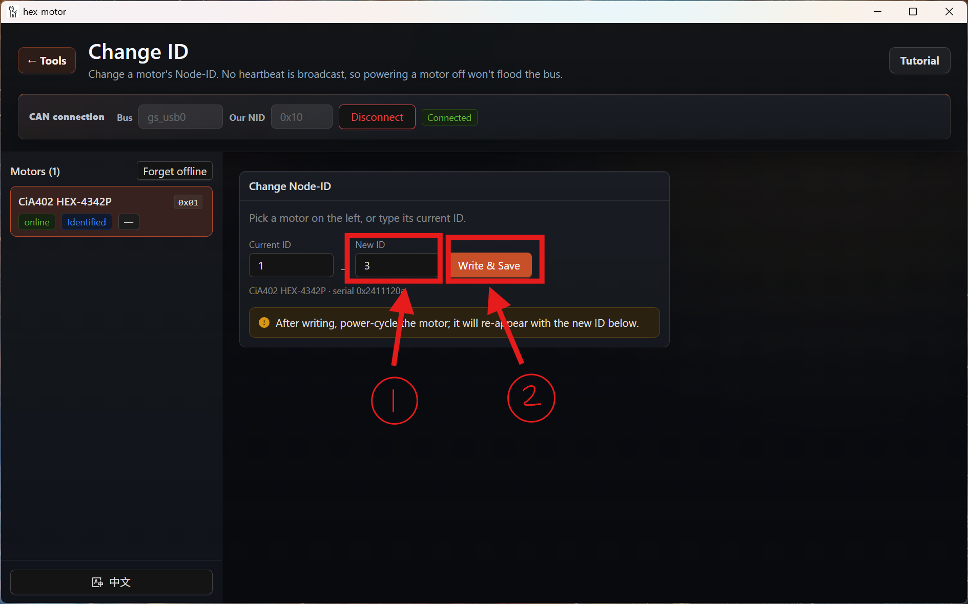
- Open the GUI and click the Change ID card.
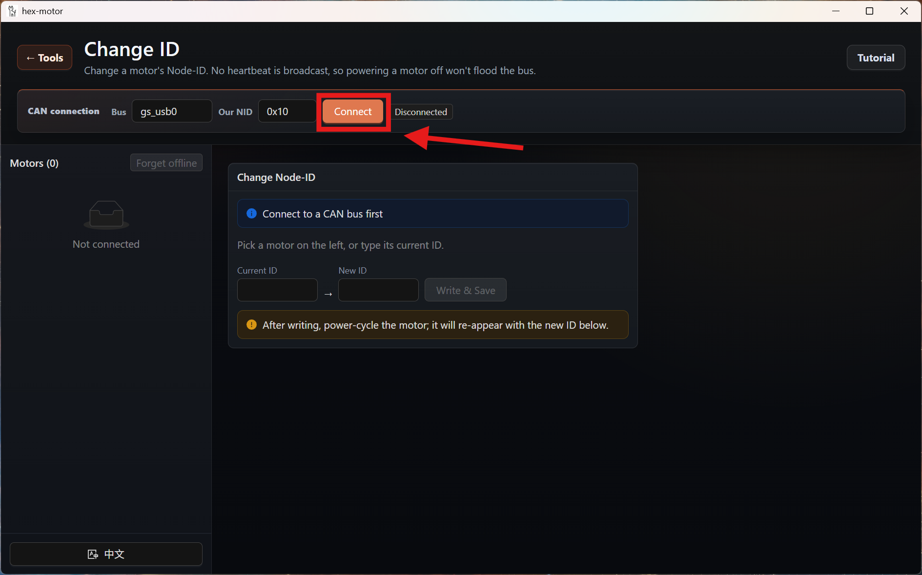
- Click the Connect button. (The input box to the left of the Connect button is the current GUI NodeID; you only need to make sure it does not clash with any motor's NodeID.)
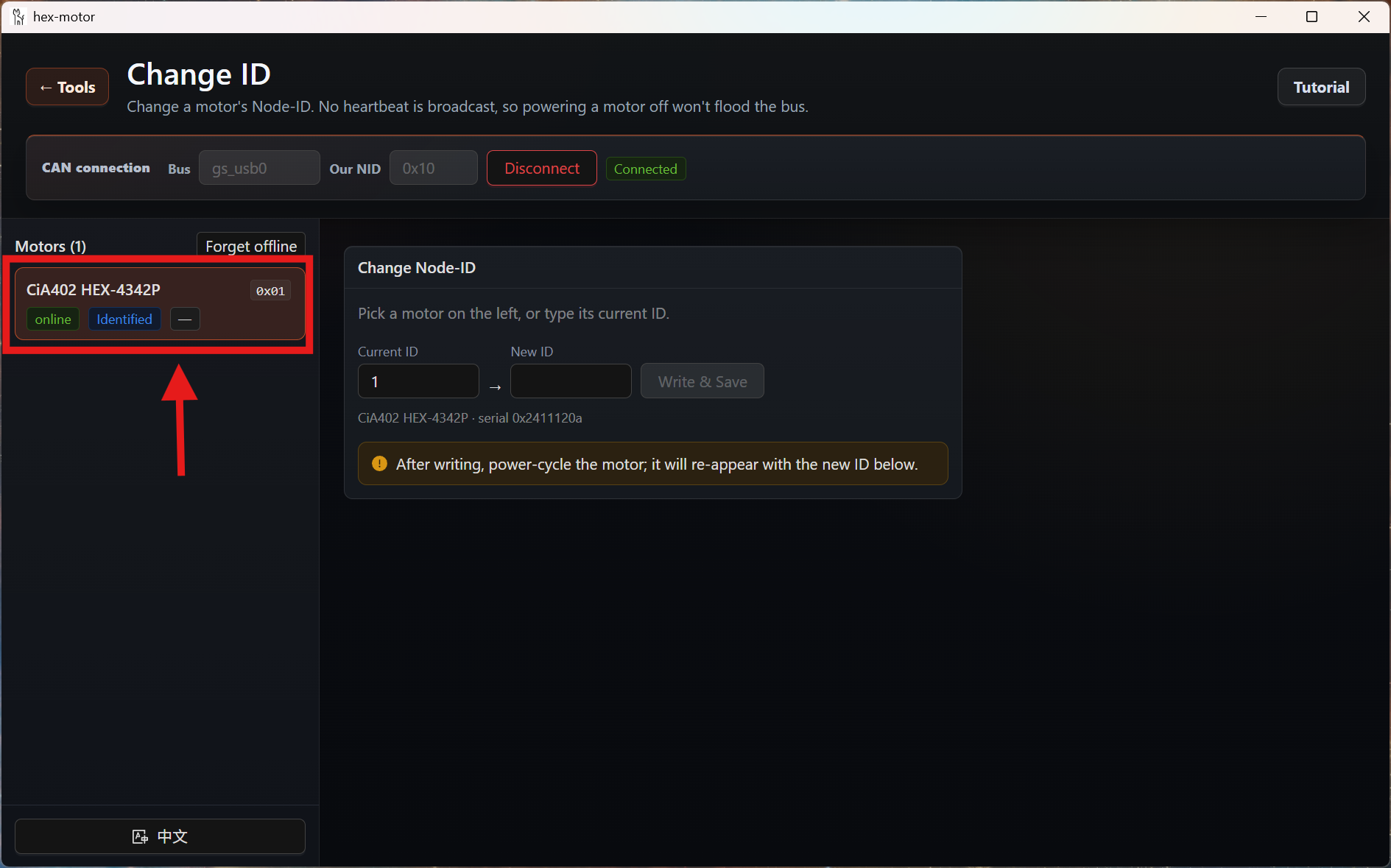
- The list on the left then shows the currently detected motors. Click the motor you want to modify.
- Enter the ID you want in the New ID box, then press the Write & Save button.
Note
After writing, power-cycle the motor and it will reappear in the list below with its new ID.
Driving a Motor with the GUI
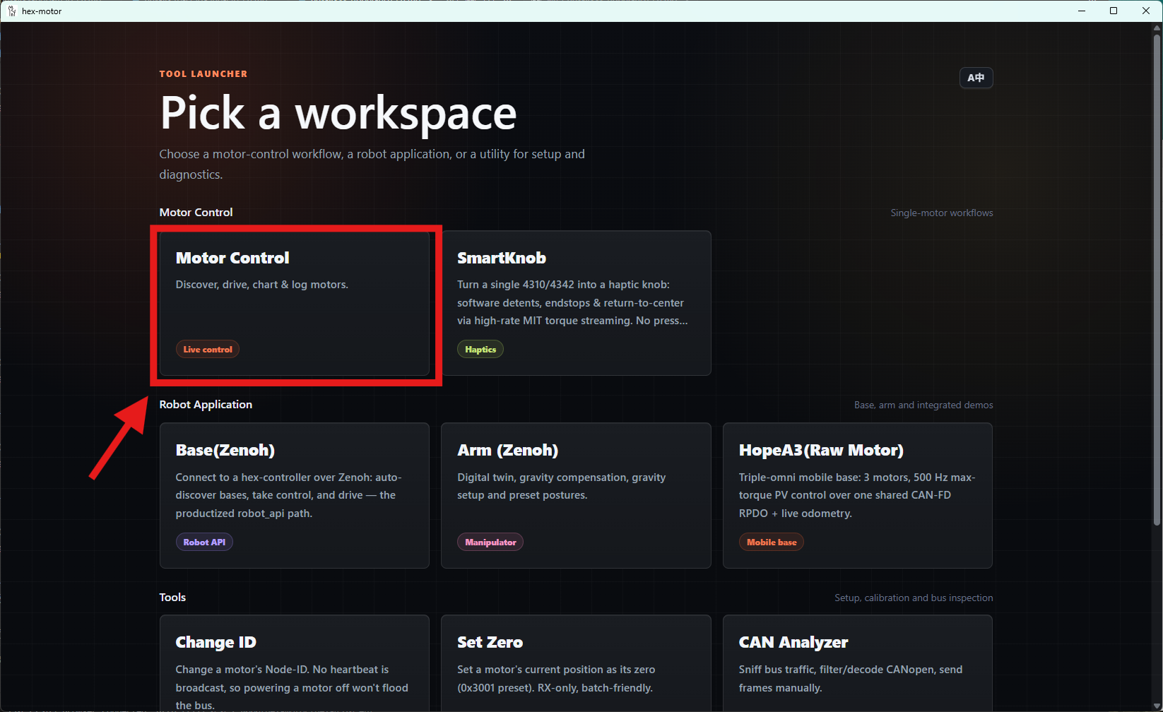
- Once you have wired everything as described above, click the Motor Control card in the GUI.
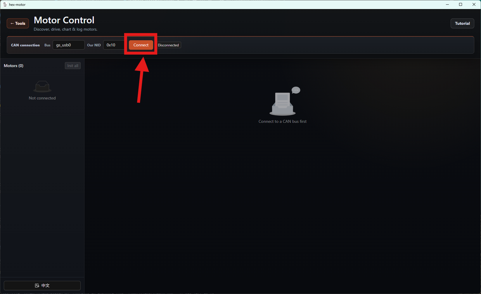
- After entering the Motor Control view, click the Connect button.
- Once the motors are connected, their information is shown in the list on the left.
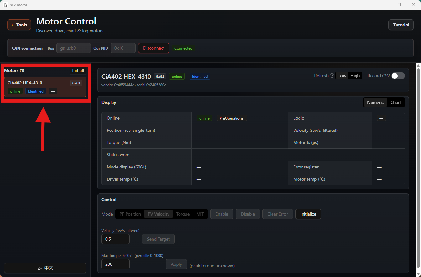
- Select the motor you want to control, then click the Initialize button.
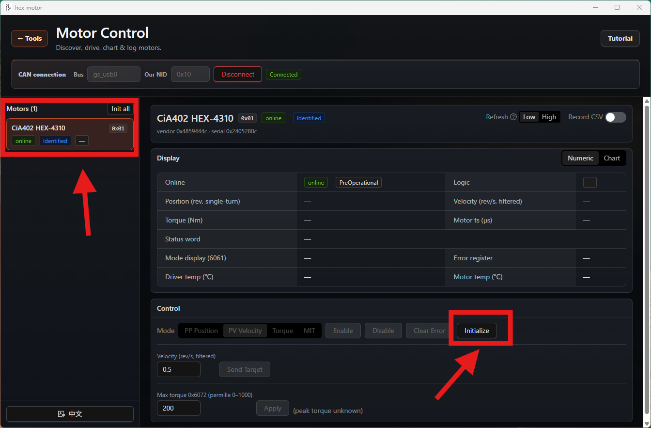
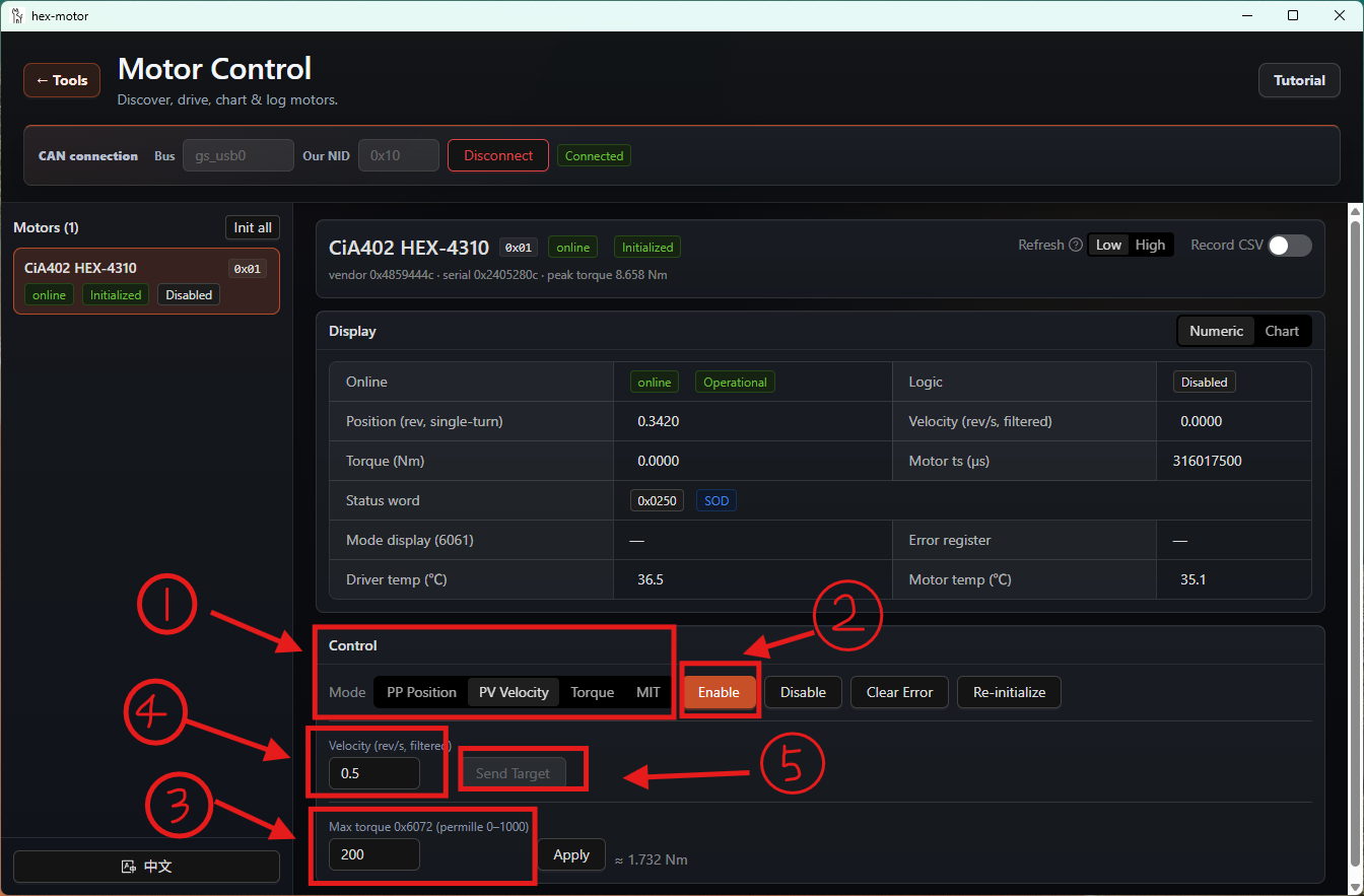
- Choose the control mode you want. Here we use velocity mode (0.5 rev/s, 30% max torque) as an example; you may choose any control mode.
The steps, in order, are: choose the control mode, enable the motor, limit the current motor's peak torque to 30% of its peak torque, set the speed to 0.5 rev/s, and send the speed.
On success you will see the motor turn.
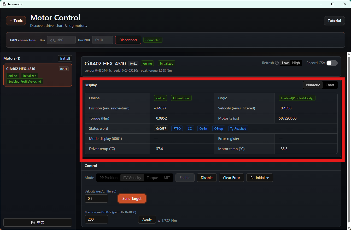
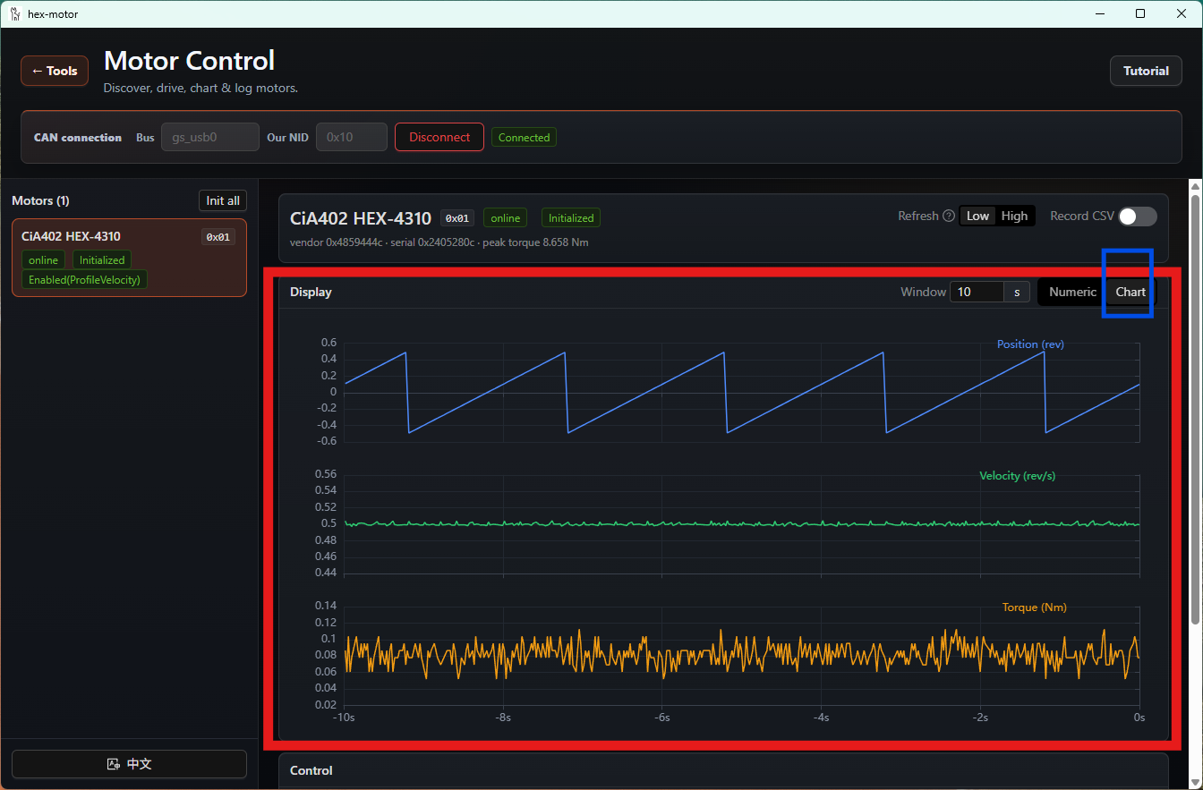
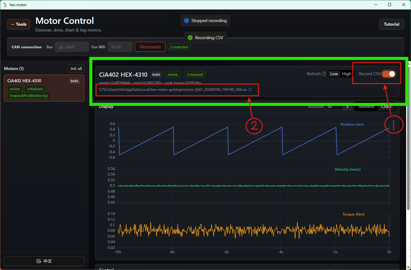
- Once the motor is running, the Display panel returns the motor's live data in real time. You can also click the Chart button to switch to chart mode.
- You can also save the motor's runtime data by pressing the Record CSV button. Box 2 marked in the image below is the file path where the runtime data is stored.
Setting the Zero Point with the GUI
You can use the GUI to set a motor's zero point.
Select the Set Zero mode.
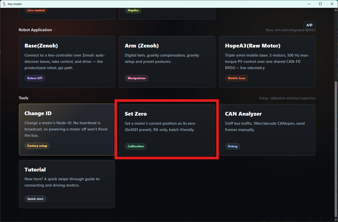
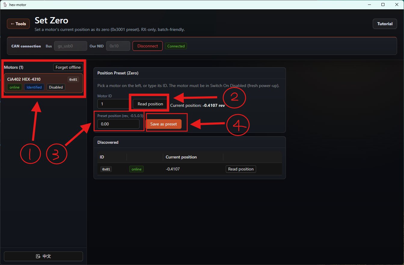
After entering it, connect the bus. Select the motor you want to modify, read the current position first, then enter the position you want to set and press the Save as preset button. No error warning means the setting succeeded.
Trying the Smart Force-Feedback Knob of hex Motors with the GUI
Select the SmartKnob mode.
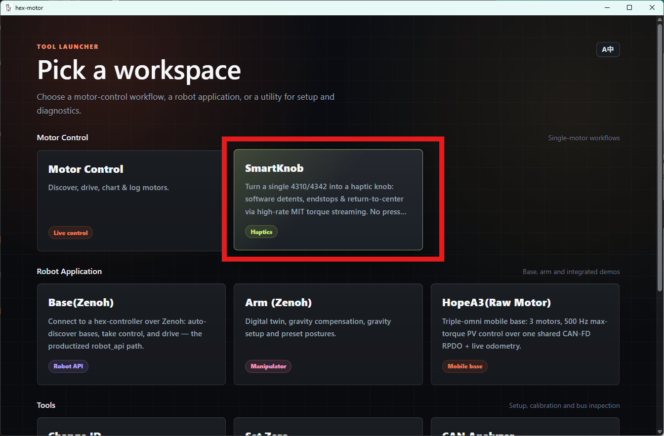
After connecting the motor, select the motor you want to operate, then pick the mode you want on the right.
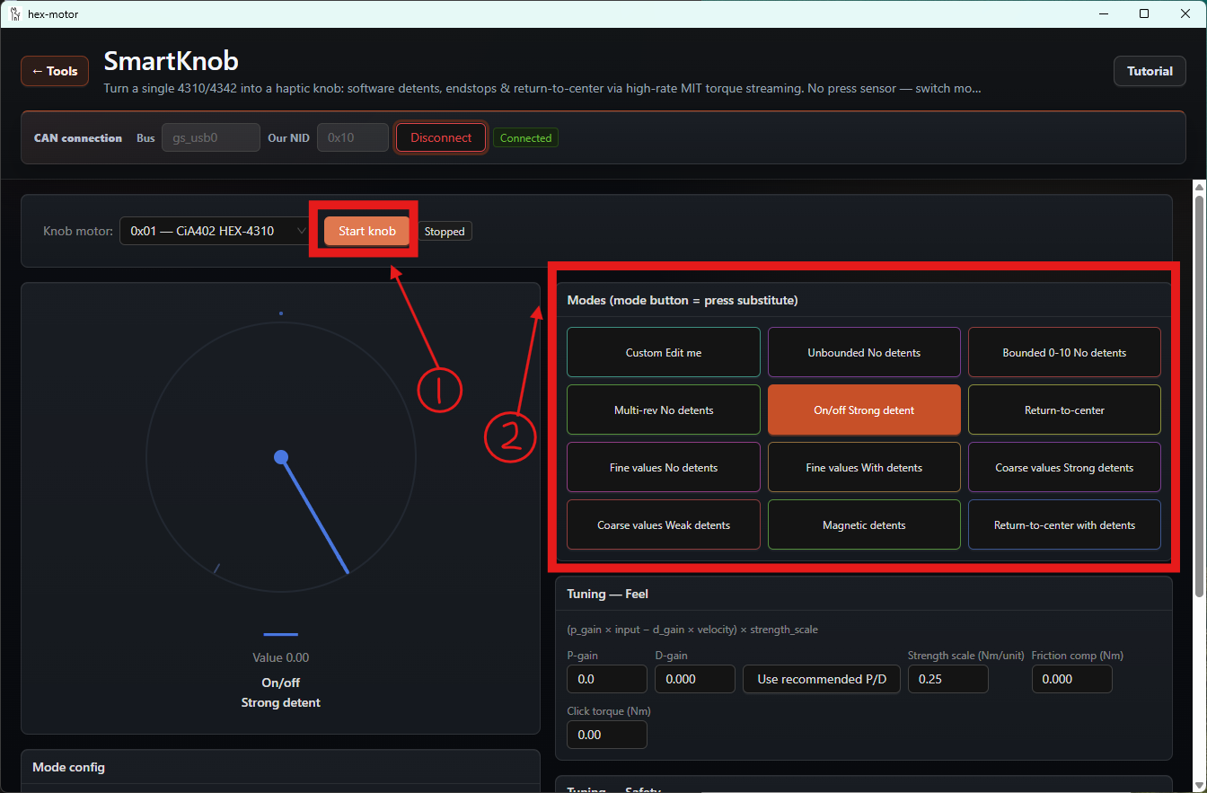
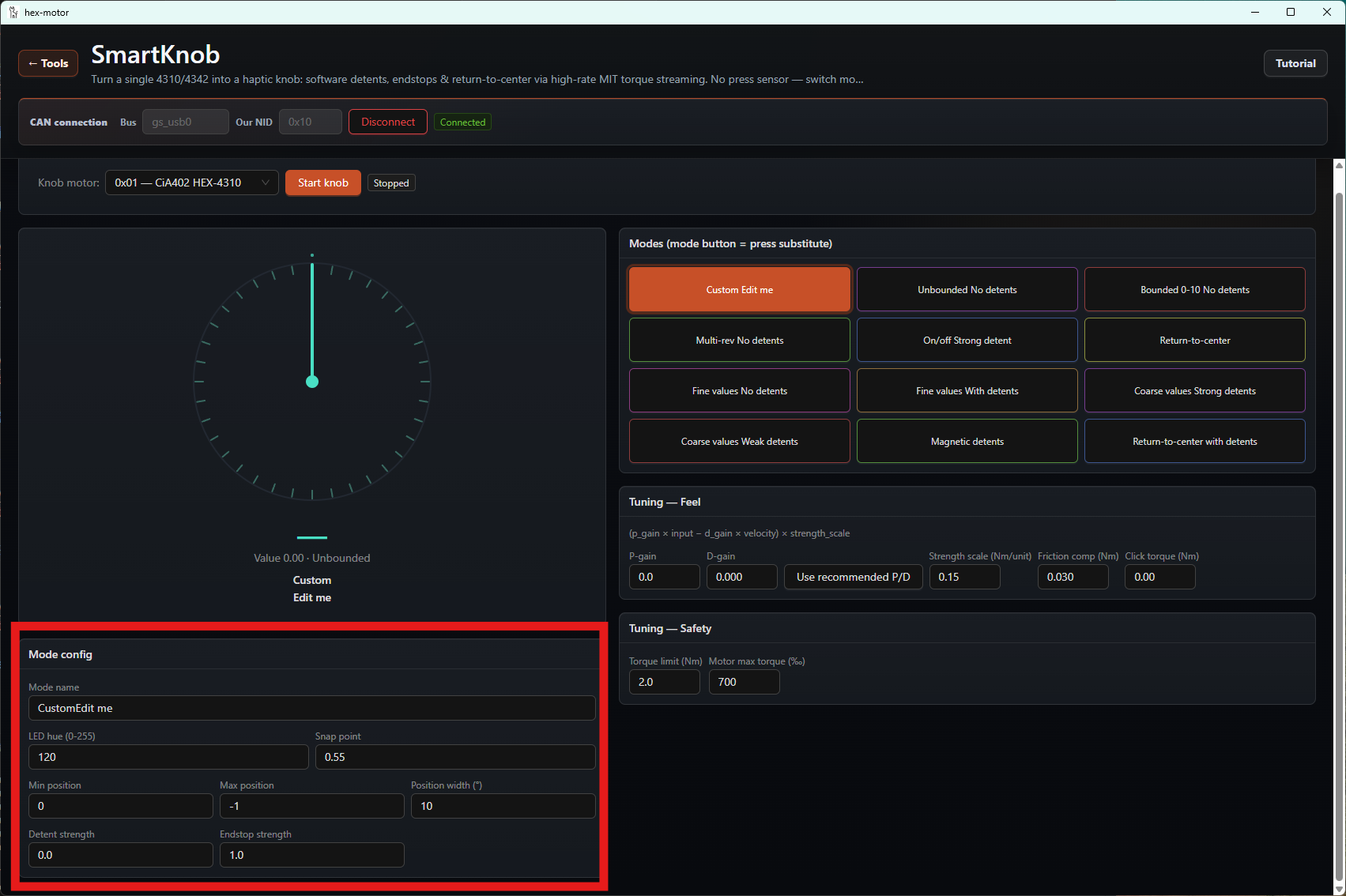
The first one is Custom mode, where you can customize the feel parameters below the dial.
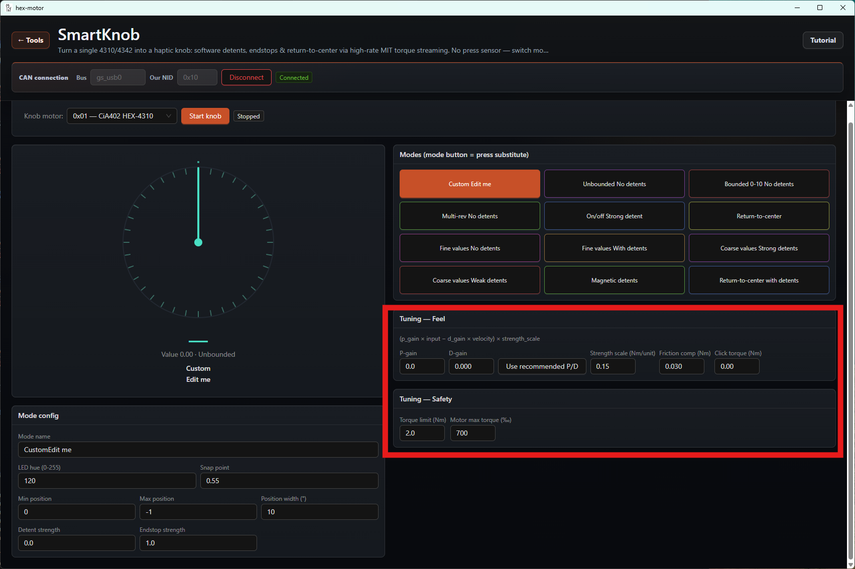
You can also adjust the feel strength of the different modes below the mode selector.
Using the GUI's CAN Data Analyzer
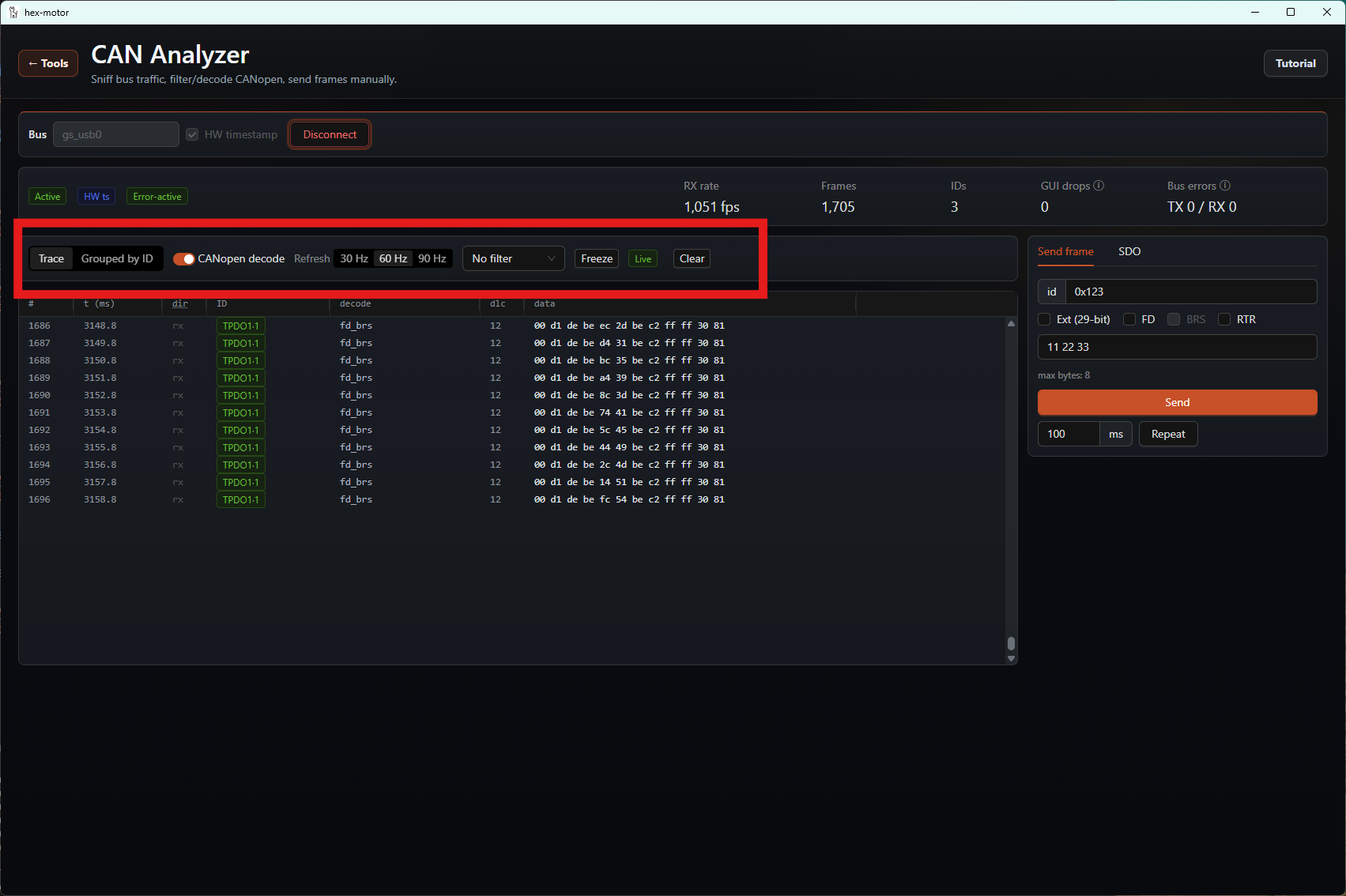
You can select the CAN Analyzer mode to inspect the messages on the connected CAN bus.
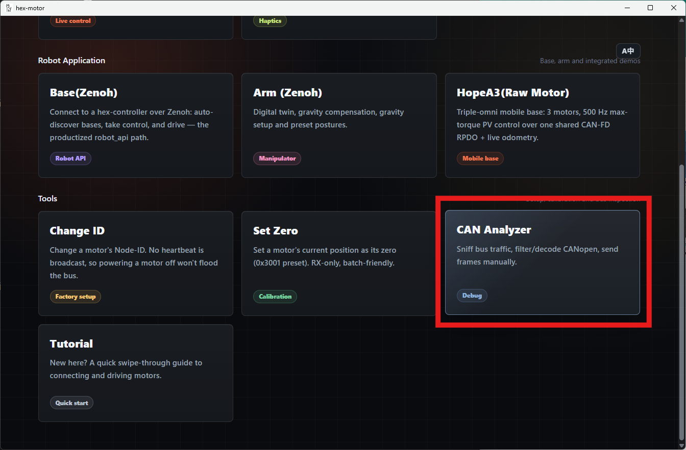
Again, you need to click the Connect button first. You can then click the various buttons to operate.