Hex 43xx upper use en
Using the GUI
The motor GUI used in this chapter requires our GUI USB hardware — the USB-CAN HUB.
Downloading the GUI
Wiring and Usage
The GUI hardware already integrates a termination resistor for every CAN interface, so when using the GUI you do not need to add a termination resistor at the GUI-side end of the CAN line — you only need to add one at the motor-side end of the CAN line.
Then connect it to your computer with a single Type-C data cable.
The CAN interface must be initialized
On Linux or macOS you must initialize the CAN interface before you can connect to the motors. See the recommended command for bringing up the CAN interface at the beginning of this document.
Changing a Motor ID with the GUI
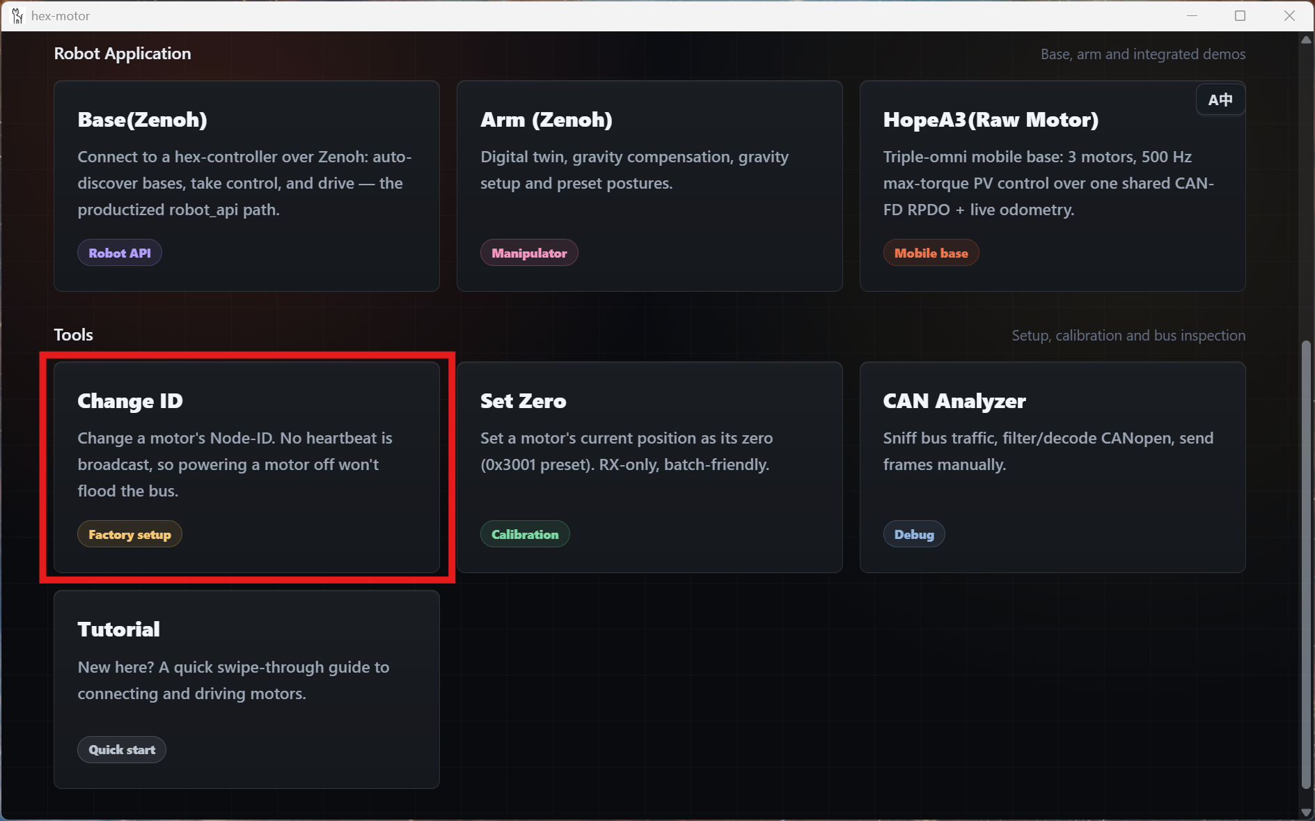
- Open the GUI and click the Change ID card.
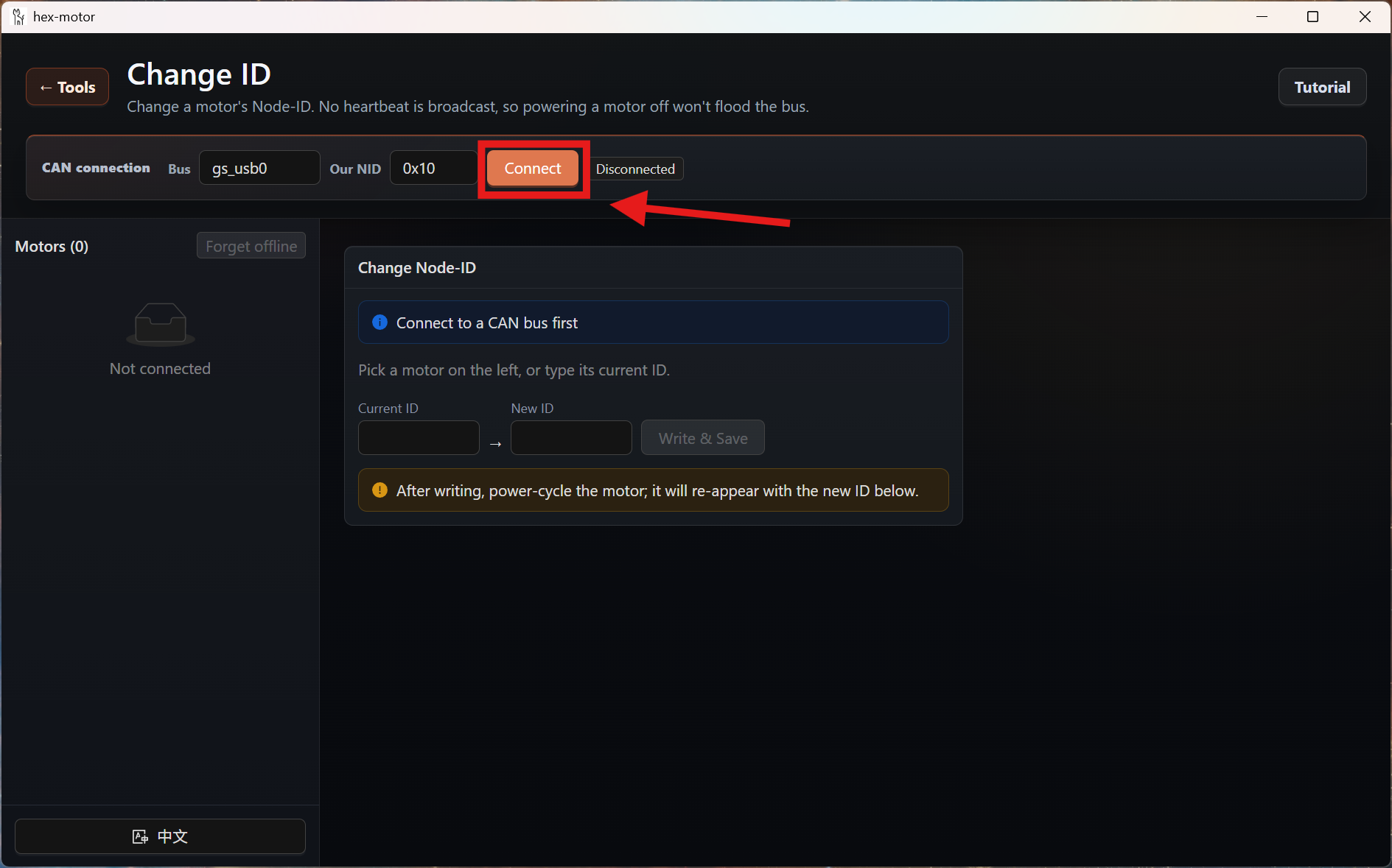
- Click the Connect button. (The input box to the left of the Connect button is the current GUI NodeID; you only need to make sure it does not clash with any motor's NodeID.)
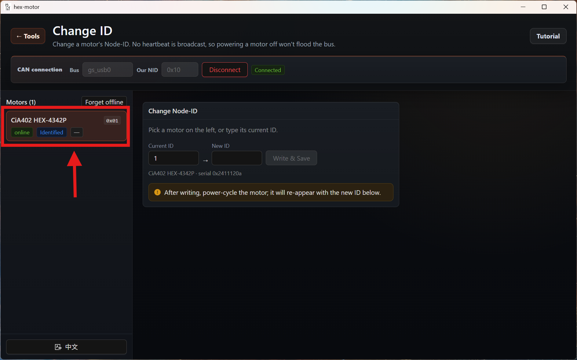
- The list on the left then shows the currently detected motors. Click the motor you want to modify.
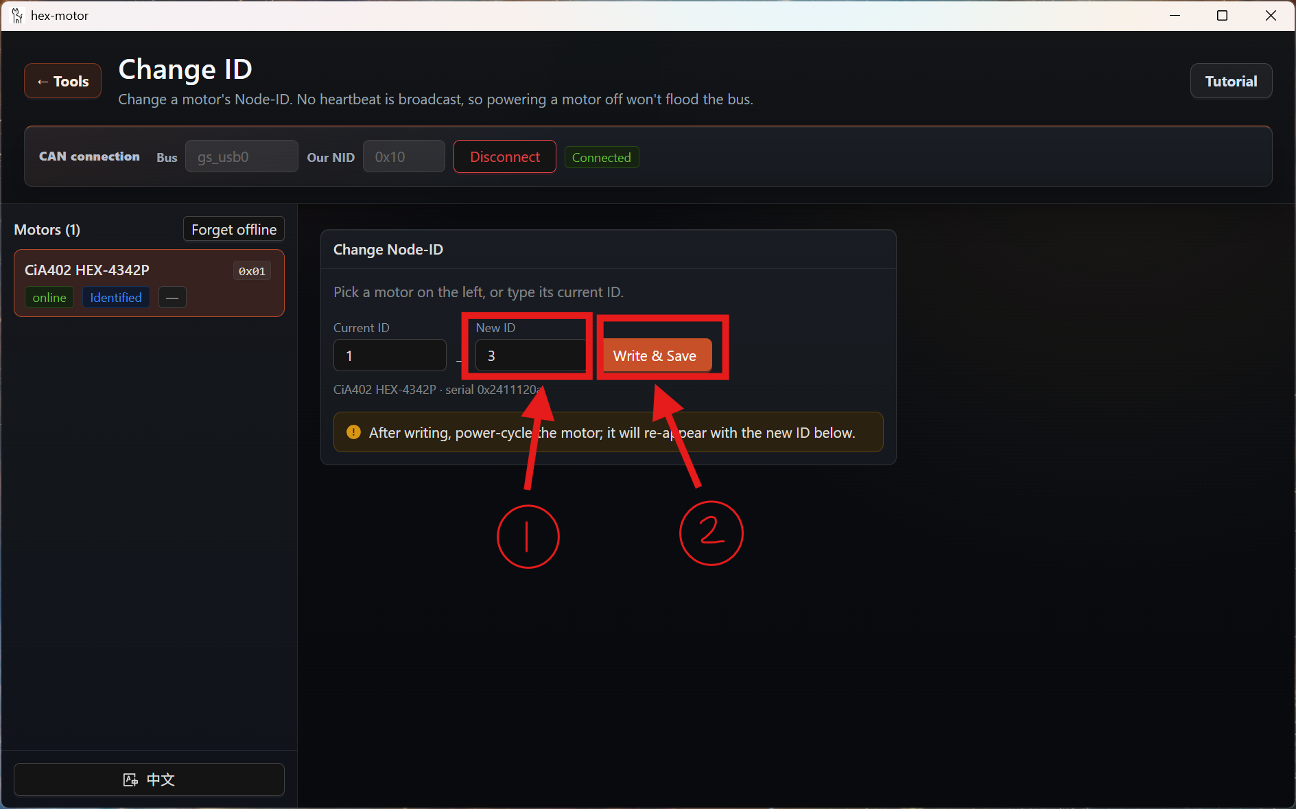
- Enter the ID you want in the New ID box, then press the Write & Save button.
Note
After writing, power-cycle the motor and it will reappear in the list below with its new ID.
Driving a Motor with the GUI
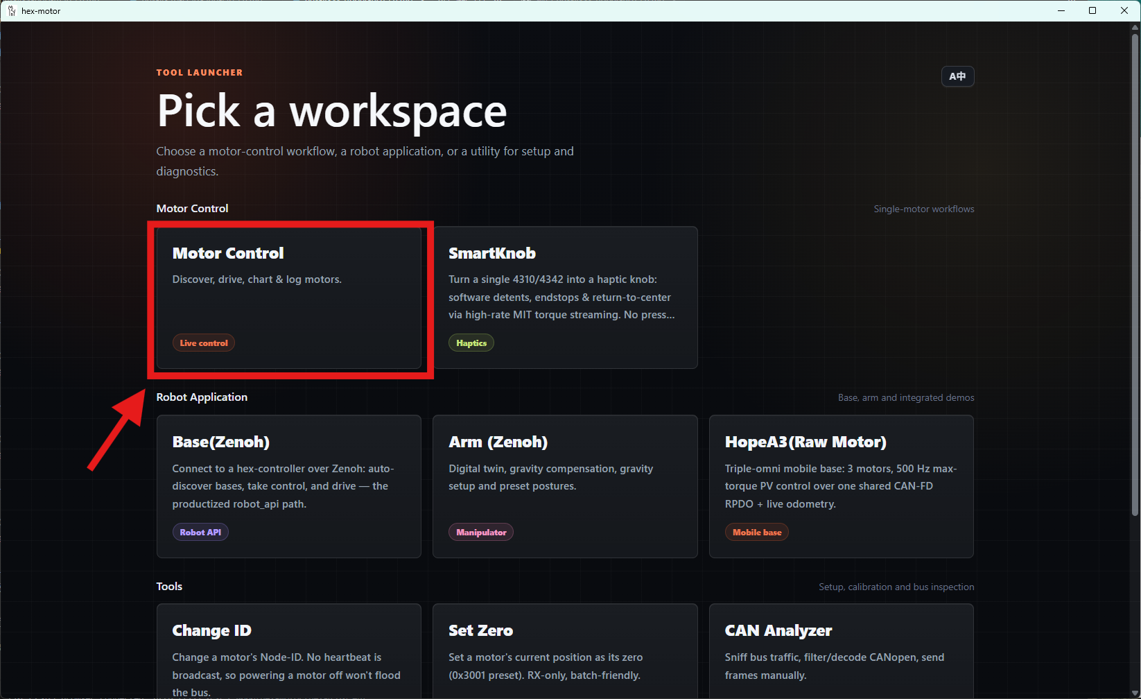
- Once you have wired everything as described above, click the Motor Control card in the GUI.
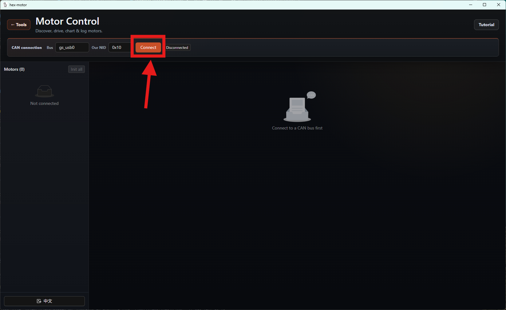
- After entering the Motor Control view, click the Connect button.
- Once the motors are connected, their information is shown in the list on the left.
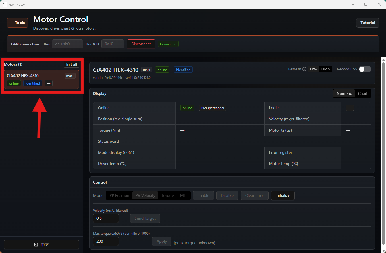
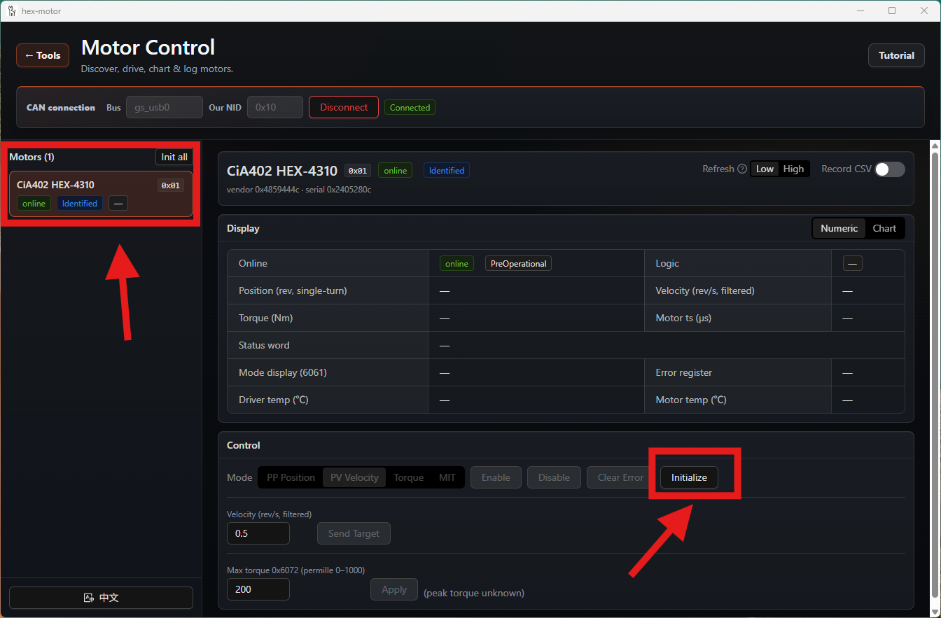
- Select the motor you want to control, then click the Initialize button.
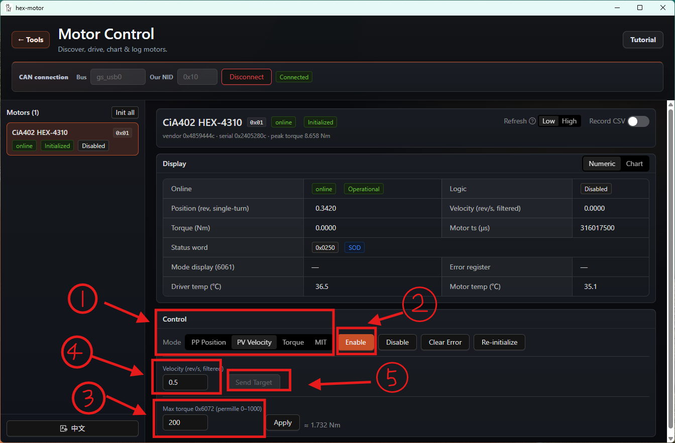
- Choose the control mode you want. Here we use velocity mode (0.5 rev/s, 30% max torque) as an example; you may choose any control mode.
The steps, in order, are: choose the control mode, enable the motor, limit the current motor's peak torque to 30% of its peak torque, set the speed to 0.5 rev/s, and send the speed.
On success you will see the motor turn.
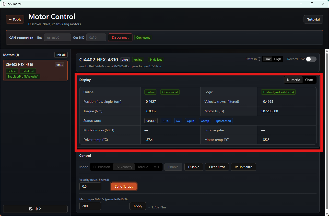
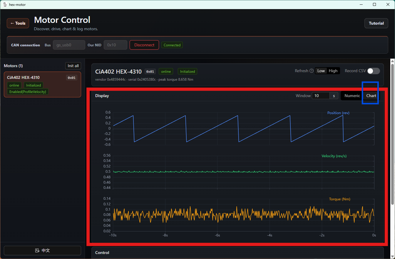
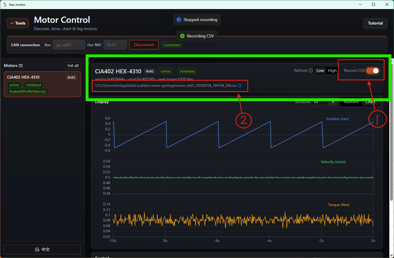
- Once the motor is running, the Display panel returns the motor's live data in real time. You can also click the Chart button to switch to chart mode.
- You can also save the motor's runtime data by pressing the Record CSV button. Box 2 marked in the image below is the file path where the runtime data is stored.
Setting the Zero Point with the GUI
You can use the GUI to set a motor's zero point.
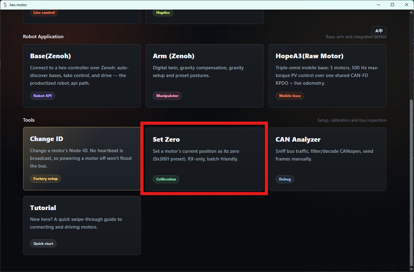
Select the Set Zero mode.
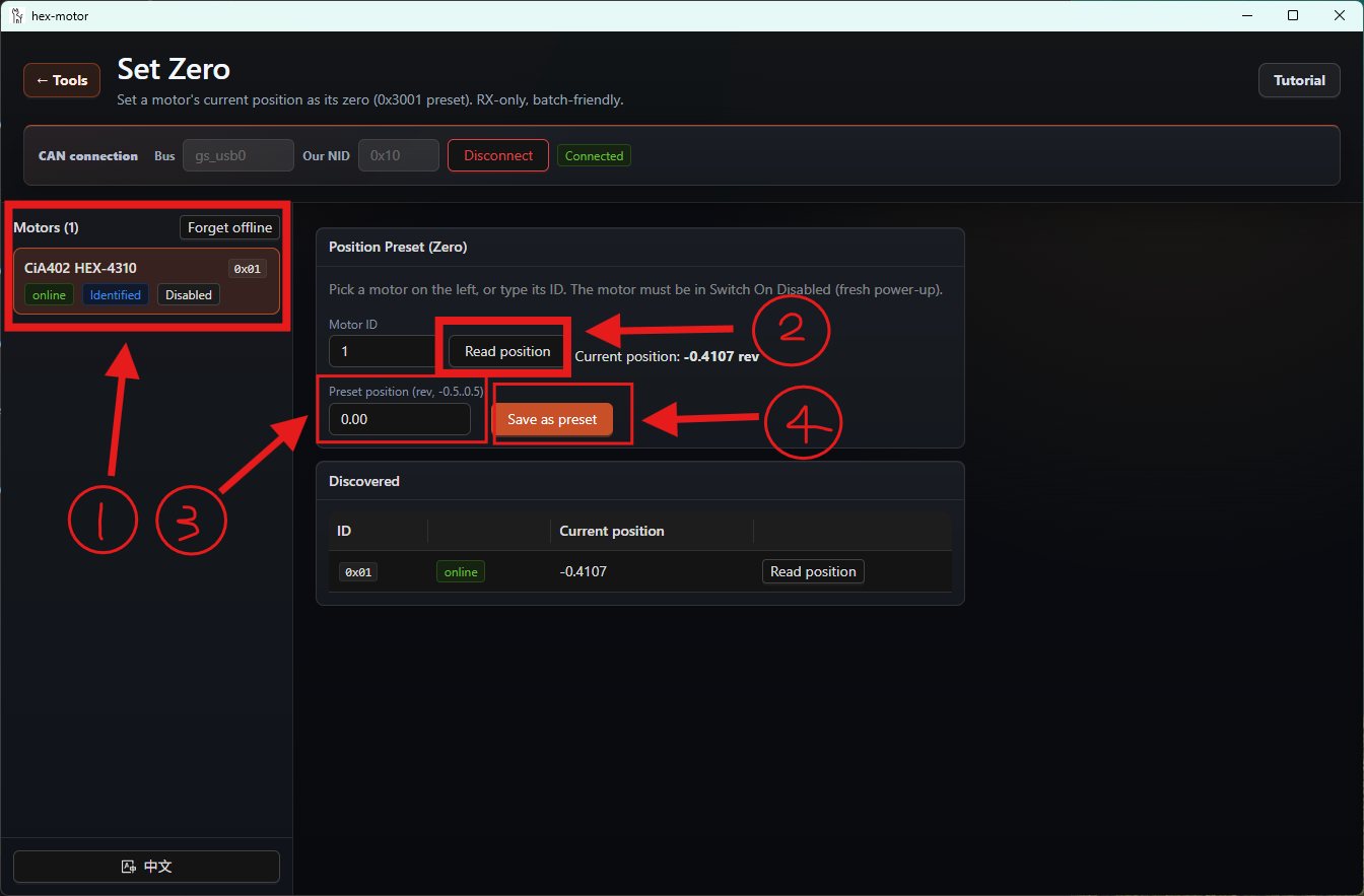
After entering it, connect the bus. Select the motor you want to modify, read the current position first, then enter the position you want to set and press the Save as preset button. No error warning means the setting succeeded.
Trying the Smart Force-Feedback Knob of hex Motors with the GUI
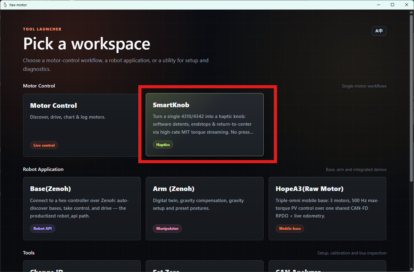
Select the SmartKnob mode.
After connecting the motor, select the motor you want to operate, then pick the mode you want on the right.
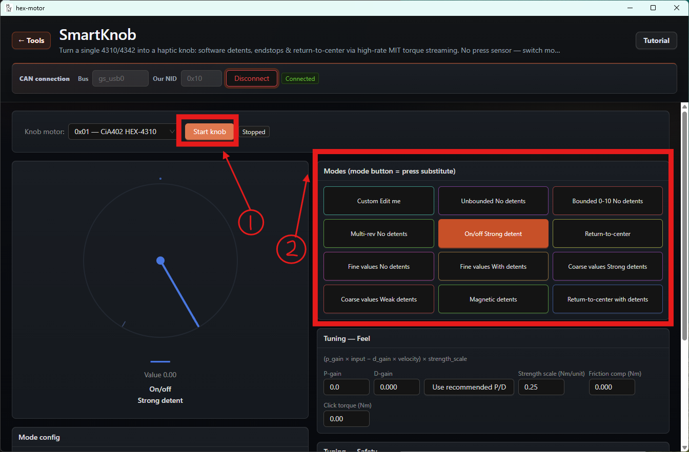
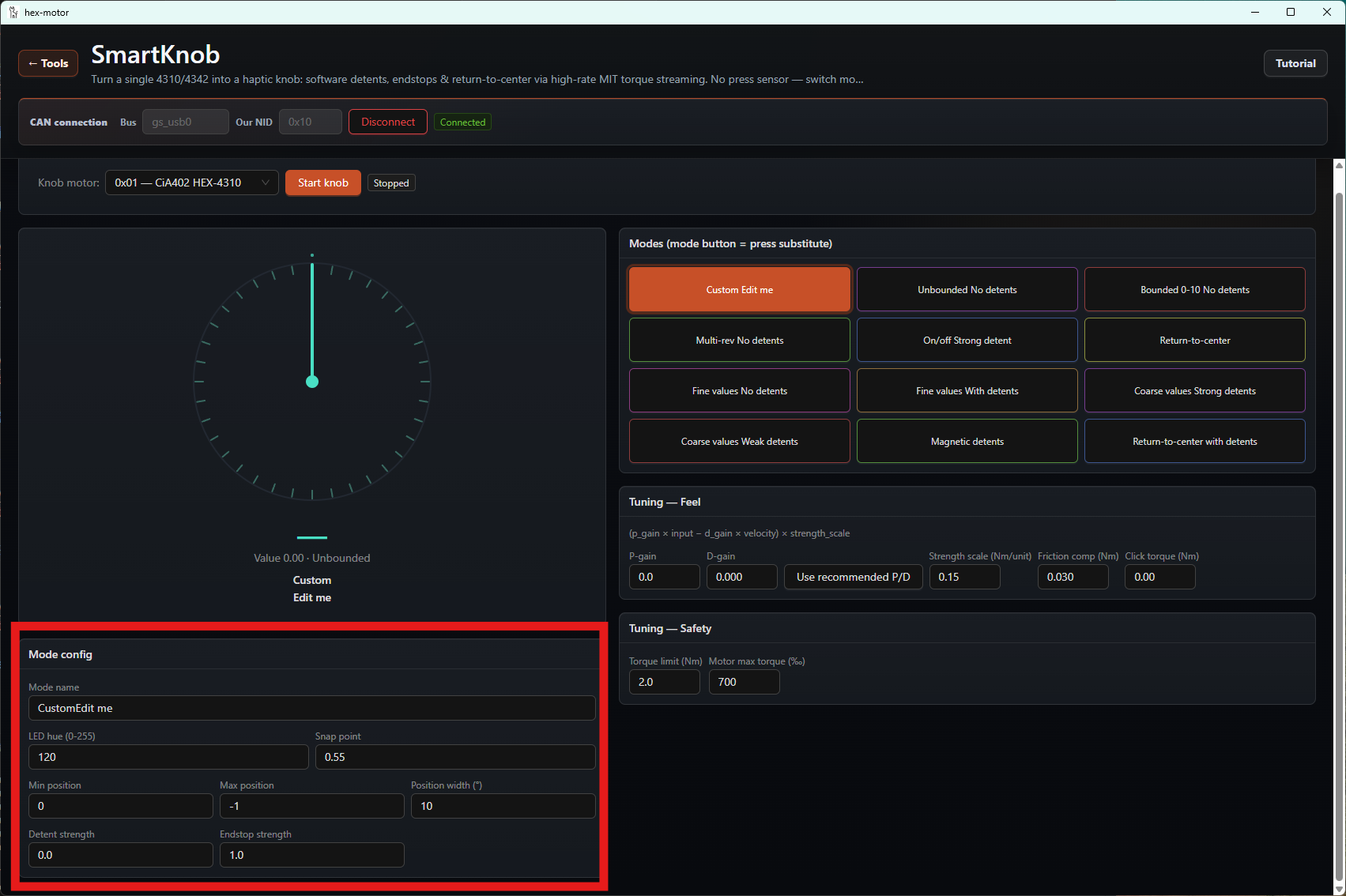
The first one is Custom mode, where you can customize the feel parameters below the dial.
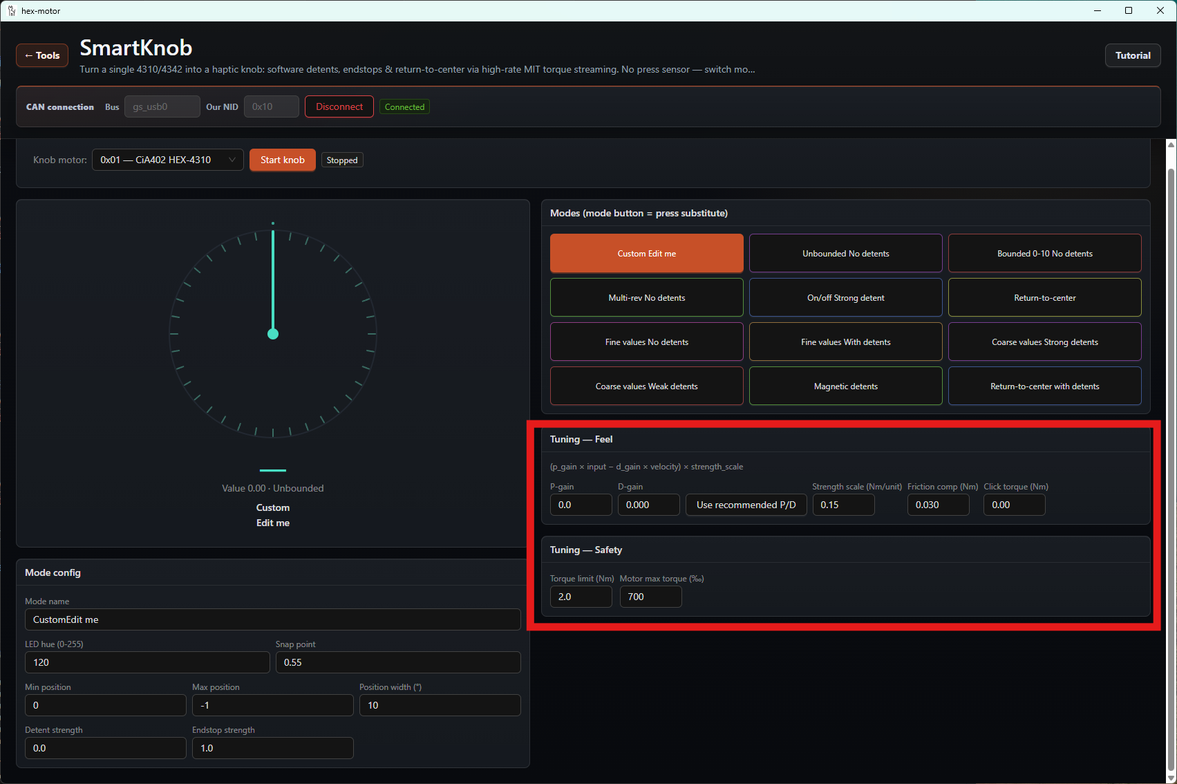
You can also adjust the feel strength of the different modes below the mode selector.
Using the GUI's CAN Data Analyzer
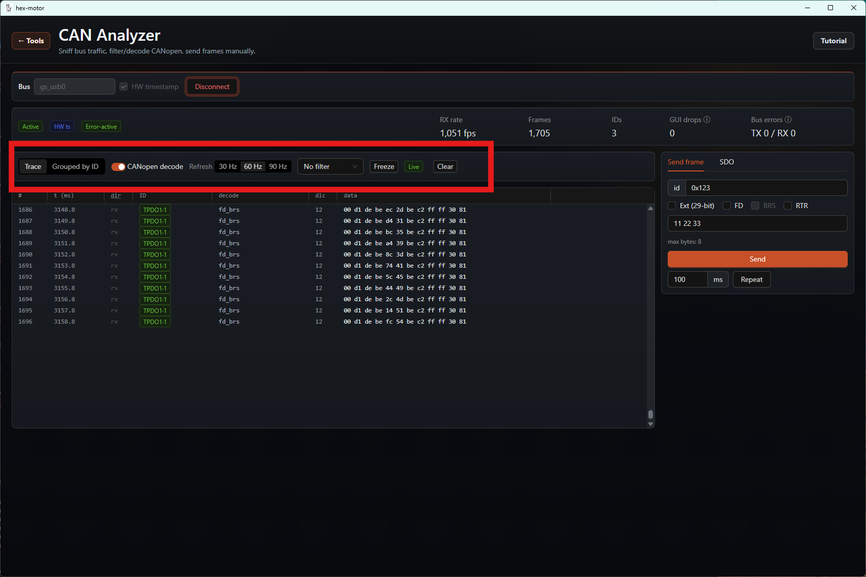
You can select the CAN Analyzer mode to inspect the messages on the connected CAN bus.
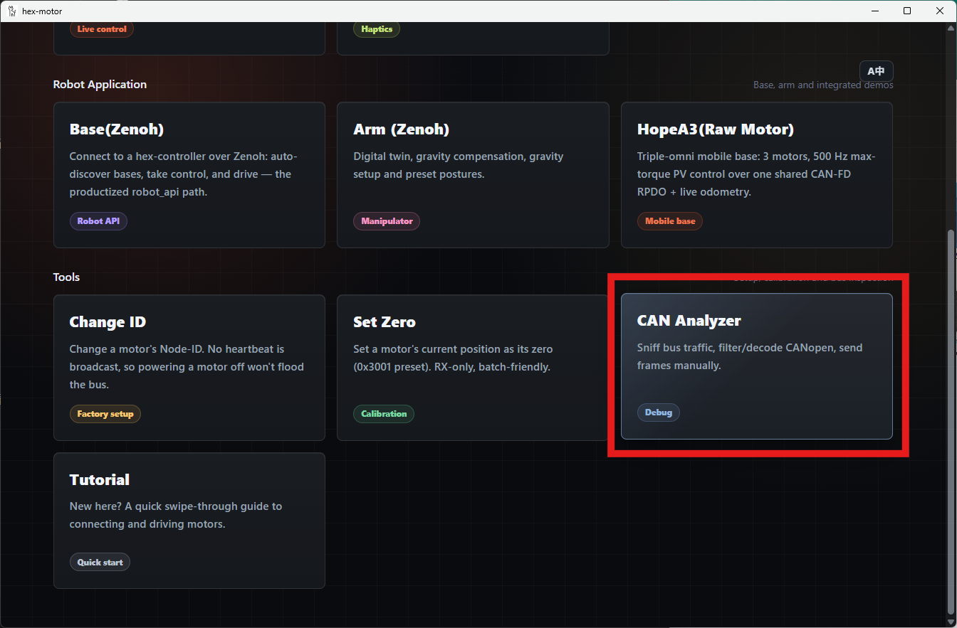
Again, you need to click the Connect button first. You can then click the various buttons to operate.